12v Led Flasher Circuit Diagram
12v Lamp Flasher Circuit Electronic Circuits And Diagrams
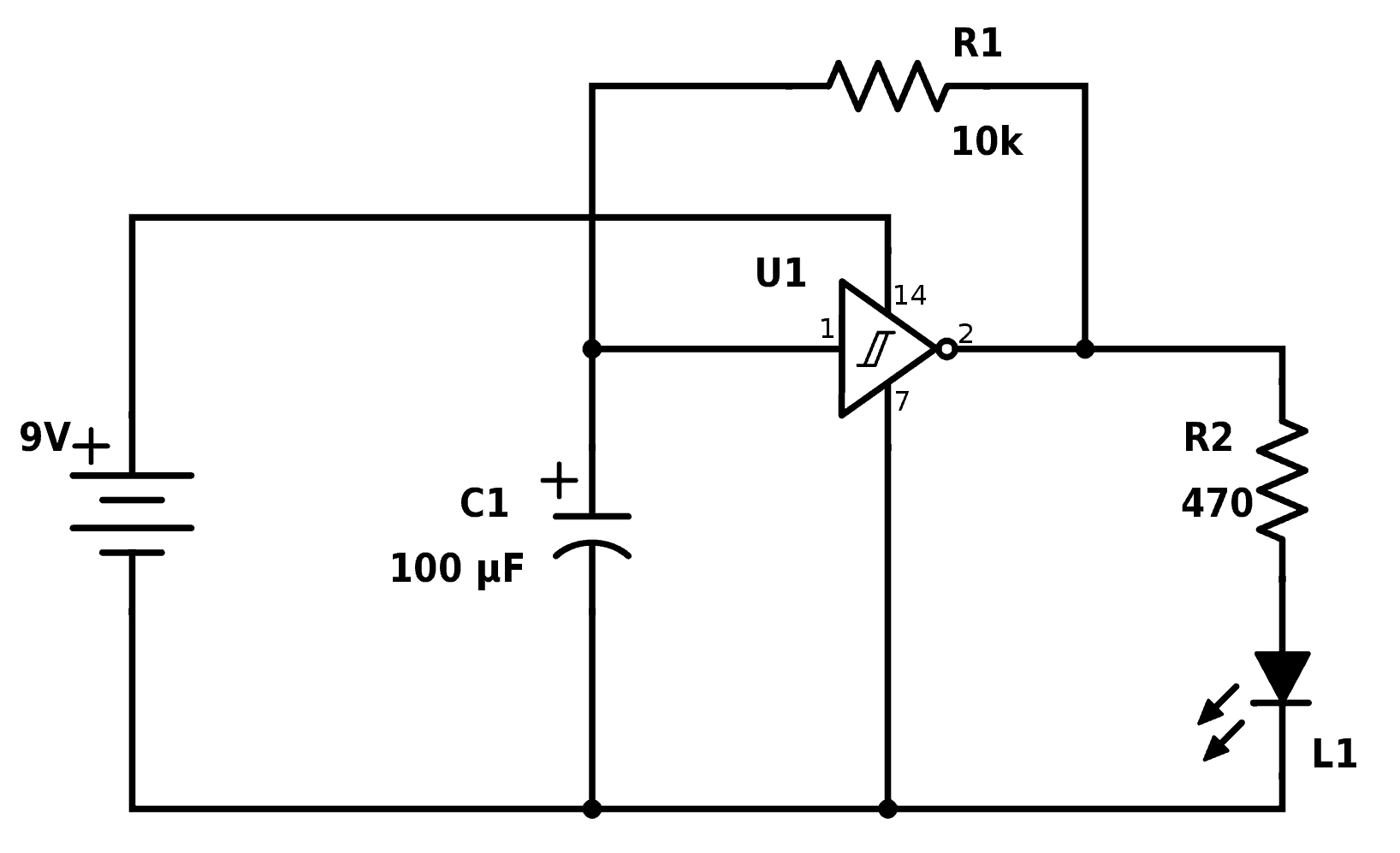
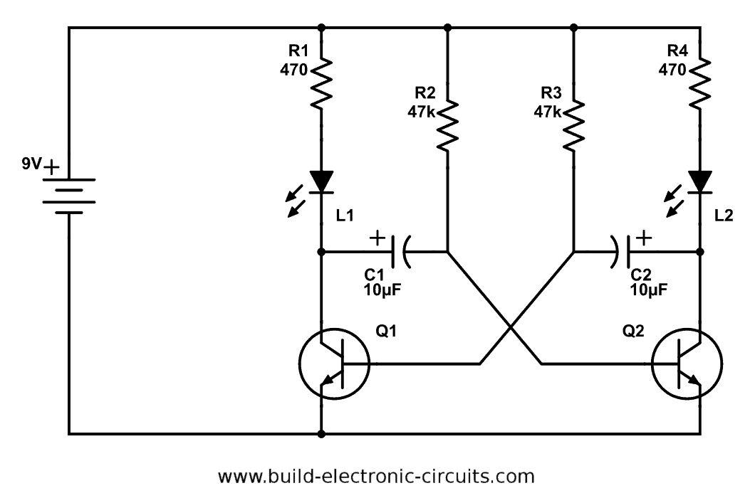
Blinking Led Circuit With Schematics And Explanation
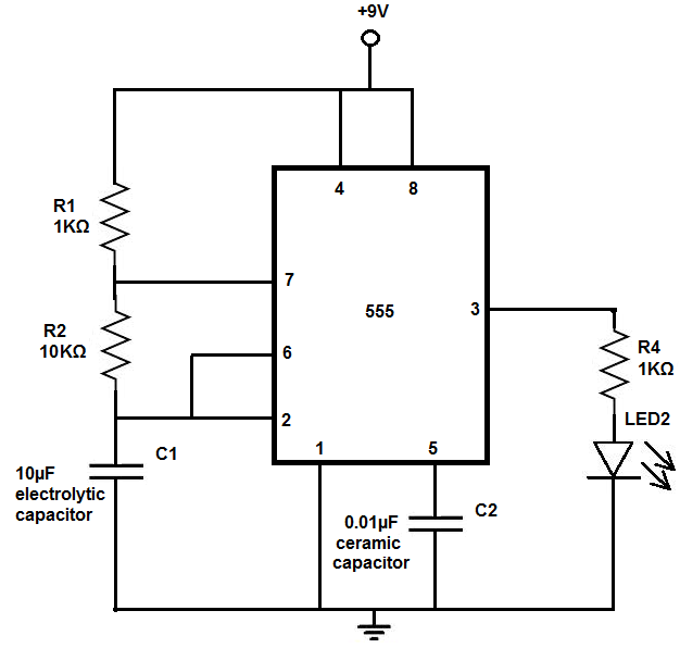
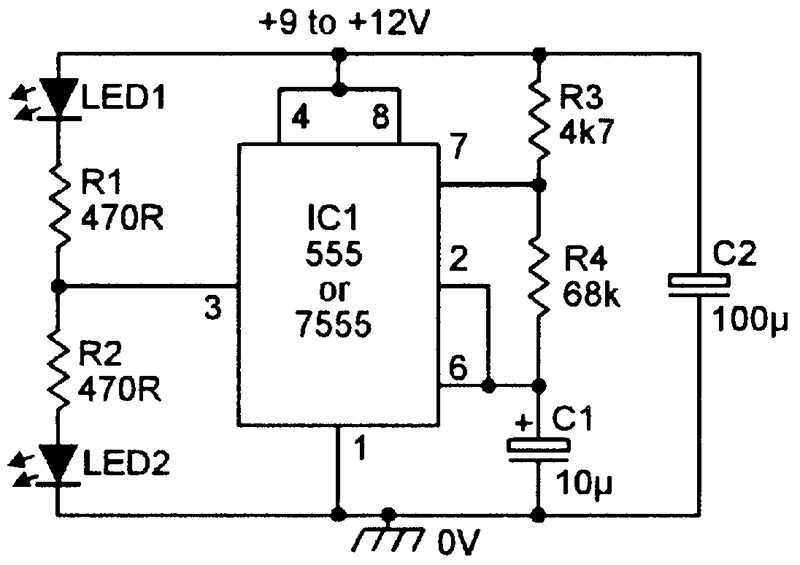
How To Build An Led Flasher Circuit With A 555 Timer Chip
12v led flasher circuit diagram best 2 pin flasher relay wiring.
12v led flasher circuit diagram. The goal is to make a light emitting diode led blink. The total time of a square wave is equal to the sum of t low and t high. Its a simple electronic circuit that gives you a visual cue if it works. This led circuit is very simple consist of 5 resistors and 15 super bright white 5mm leds which are easily available now a days on very cheap prices.
It was built using proteus and the simulation of the same will be discussed further below in this page. The blinking led circuit is like the electronics version of the hello world program. I replaced the incandescent turn signal bulbs in my kawasaki concours motorcycle with leds because 1 they brighter 2 they last longer and 3 they require less current than incandescent bulbs. You can also use this lamp circuit with.
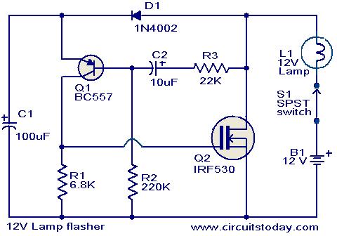
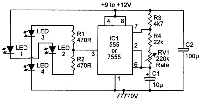
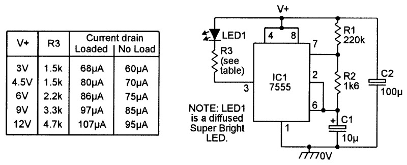
A very useful project of a 12v led lamp circuit. 12v lamp flasher circuit. The complete circuit diagram for the 24v bulb flasher relay circuit is given below. Ac mains operated single led flasher circuit built using the popular cmos timer chip tlc555 is shown below.
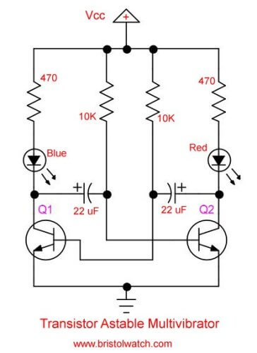
It was built using proteus and the simulation of the same will be discussed further below in this page. Because they require less current the standard fl. This is 3 channel led flasher circuit using transistor 3 step flashing effect blink one by onethe working function of this led chaser is based on to capacitor charging and discharging timing through the transistor switching. Here is a simple yet powerful circuit that can be used for flashing 12v lamps especially that is used on automobilesthe flashing circuit is based on transistor q1 bc557 and mosfet q2 irf530 where the q2 provides the necessary drive for the lampany number of bulbs can be flashed using this circuit provided.
The whole unit of this 12 volt flasher unit may be easily constructed with the help of the circuit schematic over a small piece of general pcb and can be finished within half an hour. The amount of time that the square wave is high is its duty cycle. Click on the image to enlarge and then save it to your computer by right clicking on the image. So for example if the total time of a square wave is 1 second and its high for 02s it has a duty cycle of 20 because its on for only 20 of the cycle.
Led flasher automotive or motorcycle. It was the first circuit i ever built and it felt great.

Led Chaser Led Flasher Circuit Blinking Led Circuit Diagrm
Led Flasher Chaser Circuit With Or Without Ic Electronic

Simple Led Flasher Circuit

Pin On Elektronika

Led Flasher Circuit Diagram With 555 How To Make Blinking
Practical Led Indicator And Flasher Circuits Nuts Volts
Led Flashing Circuit Schematic Flashing Led Circuit
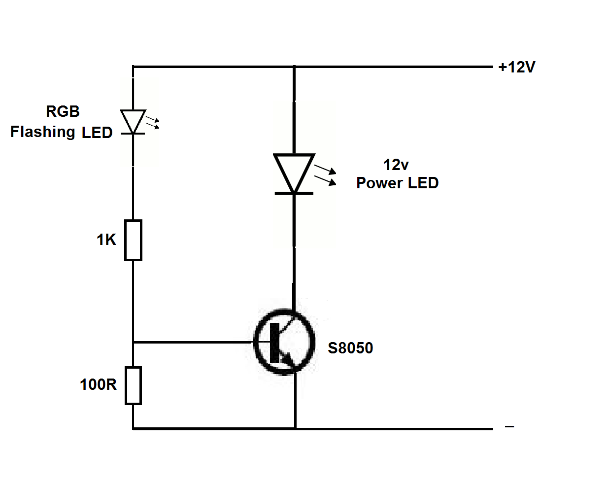
12v Power Led Flasher Circuit Using Rgb Flashing Led Hp

Pin On Circuits

Police Led Flasher Circuit With 555
Practical Led Indicator And Flasher Circuits Nuts Volts

230v Led Flasher Circuit Using Diac Circuitstune
Simple 2 Transistor Led Flasher Circuit
Led Flasher Circuit Diagram Using 555 Timer Blinking Led

Two Colour Led Flasher Circuit Using Tri Colour Led
Practical Led Indicator And Flasher Circuits Nuts Volts

Led Flasher

Led Blinker Flasher Wiring Diagram List Of Wiring Diagrams
