3pdt Wiring Schematic Board

Including layout and schematic.
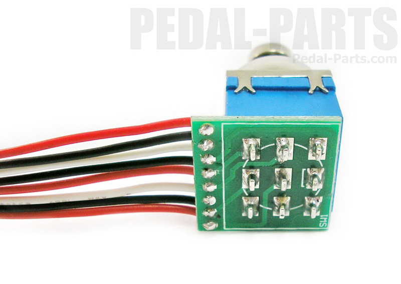
3pdt wiring schematic board. Here is the completed 3pdt wiring fig10 but what if unlike bean you are stuck in the 1970s and still use environment destroying batteries for pedals. Updated 3pdt wiring board now includes extra ground pads and is clearly labeled for beginning builders. All power wires are completely separate from audio wires in this design to create a low noise build especially in combos. Fits over a standard solder lug foot switch.
These will work with most any circuit regardless of company. Since the foot switch has two states we should. Each 3pdt wiring board contains. Foot switch wiring for guitar pedals.
Dh electro acoustics manufacturer part no. Then i did tip from in jack to 3pdt and in on schem to 3pdt. Use bi color led or standard from our shop 3 power pads to connect power to add on boards 6 ground pads perfect for combo builds. 3pdt wiring board pcb simply put the best available anywhere with 7 years of enhancements.
True bypass conversion for printed circuit board effects diagram 2 1 unsolder the wires to the spdt stock switch and install the new 3pdt. That is a small board which is what you want and will work with most any circuit. Mounts directly to foot switch and includes a spot for led resistor. Save time space on your build.
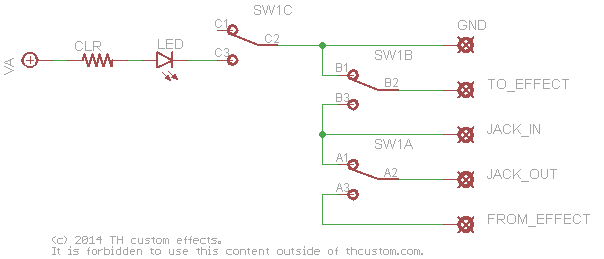
Wiring pcb board for our 3pdt foot switches with integrated led. Now lets look at a schematic representation of our bypass switching. Smallest profile most features. Dha7 this listing sale is only for pcb itself.
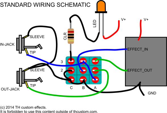
After soldering the switch and resistor simply connec. 2 cut the brown wire at x where it meets the pcb quick disconnect and tape off the cut off wire coming from the connector. Then tip from out jack to 3pdt and out on schem which is middle of vol pot to 3pdt. Works with our 3pdt with led or standard 3pdt foot switches omit the resistor and do not connect power if using a regular switch.
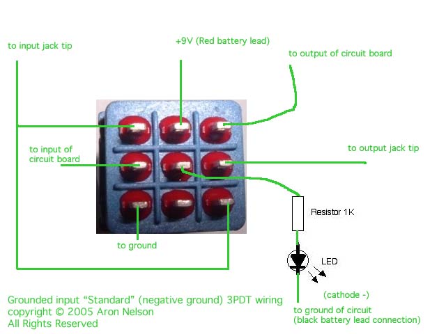
3pdt footswitch diy pcb wiring board switch manufacturer. The third solder place one the plug i didnt use. This pcb makes wiring the 3pdt footswitch easier theres also room for a led and resistor the dimensions of the pcb are 24x24mm this project is b. I did the 3pdt wiring like my picture and placed the shield of the plug adapter where the schem says 9v then grounded the tip of the plug.
Fits all standard 3pdt pcb and solder lug foot switches. But in the diagram it shows each pot going to a vero board so heres the question.


