4 1 Multiplexer Logic Diagram
Multiplexer And Demultiplexer Circuit Diagrams And Applications

Multiplexer Mux And Multiplexing Tutorial
Digital Circuits Multiplexers Tutorialspoint
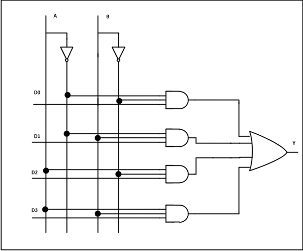
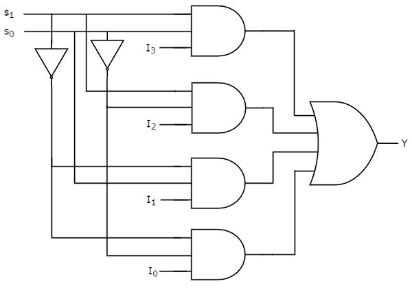
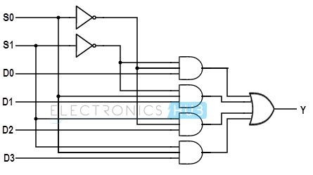
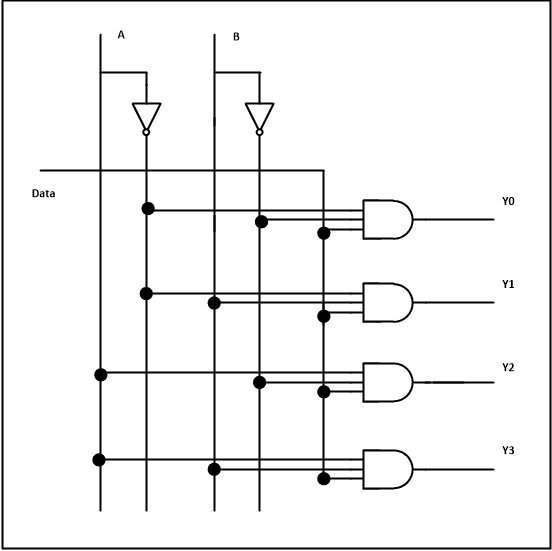
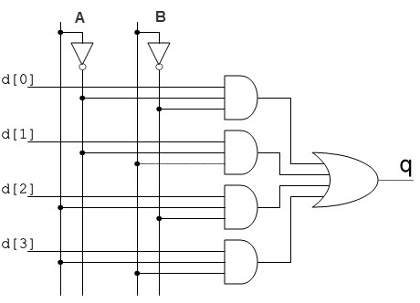
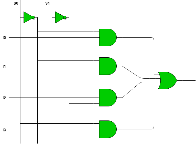
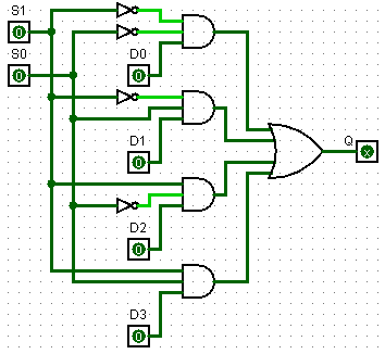
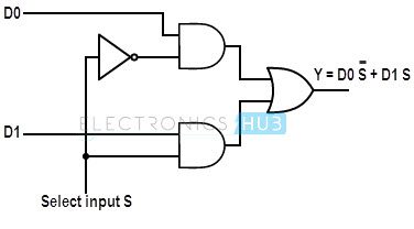
To implement this via logic ciruit diagram we need to use the combination of and or logic gates.
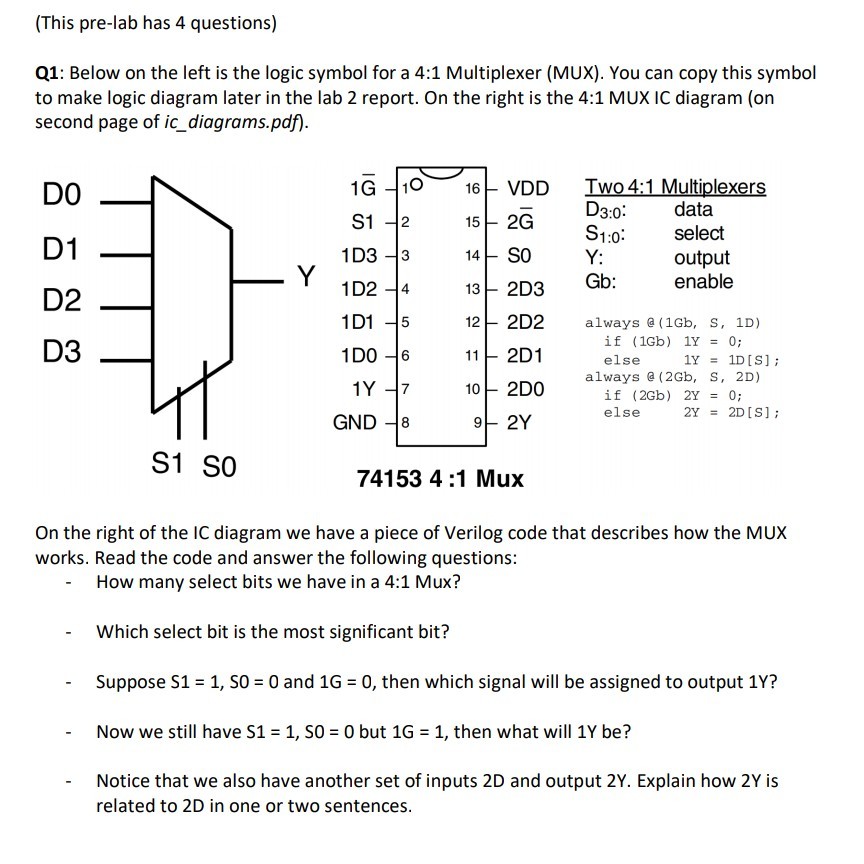
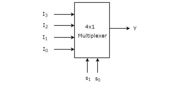
4 1 multiplexer logic diagram. In 41 mux there will be 4 input lines and 1 output line. And to control which input should be selected out of these 4 we need 2 selection lines. Circuit diagram of 4 to 1 multiplexer we can draw the circuit diagram of 4 to 1 multiplexer by using two 2 to 1 multiplexer. We can use another 41 mux to multiplex only one of those 4 outputs at a time.
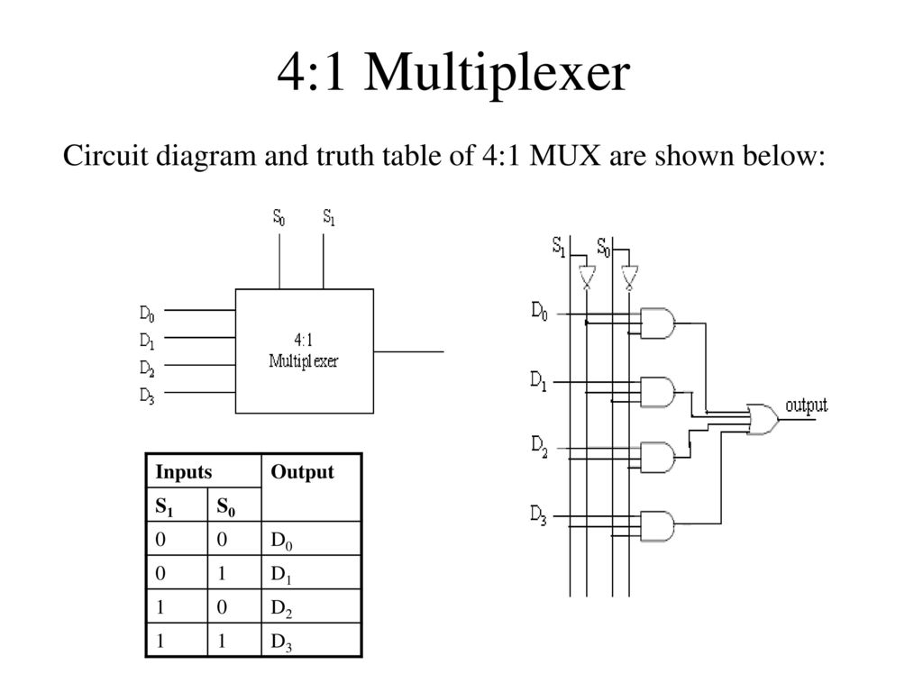
Few types of multiplexer are 2 to 1 4 to 1 8 to 1 16 to 1 multiplexer. A multiplexer is a combinational circuit it is a type of circuit whose output rely on the given inputs using various logic gates that takes multipleto construct a 4 to 1 multiplexer we need to know how many selection lines we required to create a mux. Learn how to draw the block diagram of 4 to 1 multiplexerfunction and truth table of 4 to 1 multiplexerworking of 4 to 1 multiplexer and logic diagram of 4 to 1 multiplexer. The truth table of a 4 to 1 multiplexer is shown below in which four input combinations 00 10 01 and 11 on the select lines respectively switches the inputs d0 d2 d1 and d3 to the output.
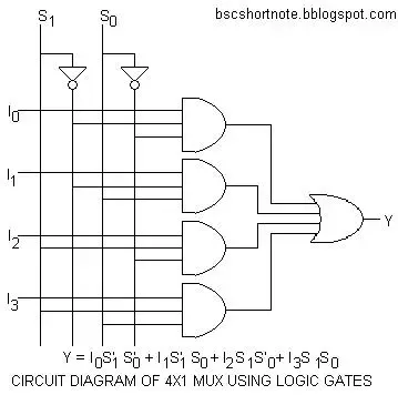
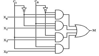
Above diagram is of sop sum of products type. It is possible to make simple multiplexer circuits from standard and and or gates as we have seen above but commonly multiplexersdata selectors are available as standard ic. So at the least you have to use 4 41 mux to obtain 16 input lines. The multiplexer used for digital applications also called digital multiplexer is a circuit with many input but only one output.
By applying control signals we can steer any input to the output. But youd then have a logic with 4 output pins. In this article we will discuss the designing of 41 mux with the help of its circuit diagram input line selection diagram and truth table. In a 41 mux you have 4 input pins two select lines and one output.
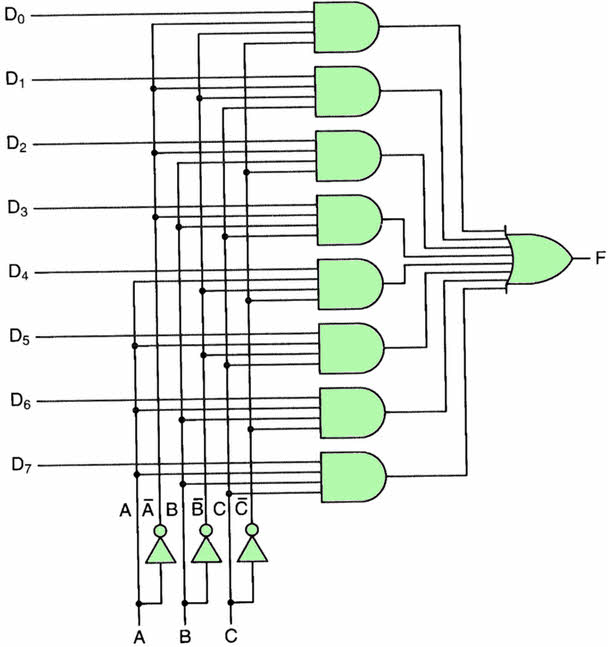
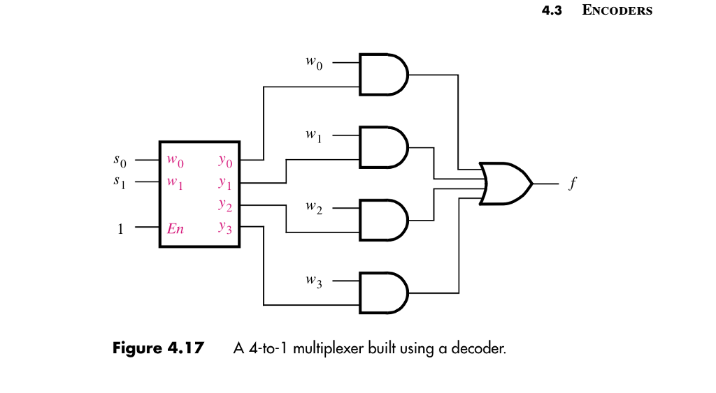
For digital application they are built from standard logic gates. Packages such as the common ttl 74ls151 8 input to 1 line multiplexer or the ttl 74ls153 dual 4 input to 1 line multiplexer. 8 1 multiplexer logic diagram the conceptual diagram of the describe a one bit 4 to 1 multiplexer. The figure below shows the block diagram of a 4 to 1 multiplexer in which the multiplexer decodes the input through select line.

Multiplexer Mux And Multiplexing Tutorial
Multiplexer Mux And Multiplexing
Multiplexer And Demultiplexer Circuit Diagrams And Applications
How To Design A 4 By 1 Multiplexer Using Nand Or Nor Gates
Multiplexer And Demultiplexer Circuits And Apllications
Read E Book Online 8 1 Mux Logic Diagram Epanel Digital Books

Multiplexer Mux And Multiplexing Tutorial

Enjoy The Electronics 4 1 Multiplexer
Multiplexers Digital Electronics Geeksforgeeks

What Is Multiplexer How It Works Multiplexer Circuit

How Do To Implement Full Subtractor Using 4 1 Multiplexer
What Is Demultiplexer Different Types Of Demultiplexers
Plc Program To Implement 4 1 Multiplexer Sanfoundry
Digital Circuits Multiplexers Tutorialspoint
What Is Multiplexer And De Multiplexer Types And Its
Solved 3 Implement A 4 1 Multiplexer Using A 2 4 Decoder
Multiplexer Mux And Multiplexing
4 1 Multiplexer Mini Projects Electronics Tutorial
