Allan Timer Schematic Diagram
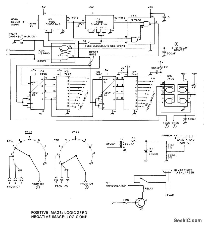
Programmable industrial timer circuit diagram circuit description.
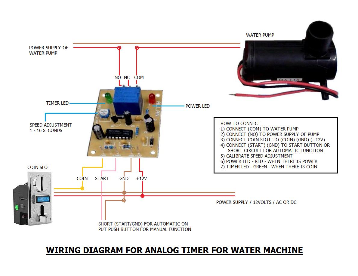
Allan timer schematic diagram. In this video im gonna show how to easily replace a relay on a timer board i used this to. Replacing a busted relay on a timer is much cheaper than buying a new timer for your arcade machines. Perkins builder brothers 1005143 views. How to bring ni cad drill batteries back to life make them charge again ryobi duration.
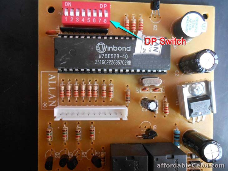
Thanks ill go buy the bits tomorrow and give it all a try. Pisonet software timer free diagram credits to. Frugalpreppers garage garden 1525303 views. This article will teach us how to adjust allan timer settingsallan pisonet timerallan timer manualallan timer diagrampisonet timer diagrampisonet timer settings that usually used in pisonet.
Nov 7 2015 1. This timer circuit is designed to switch on a 12 v load in a solar powered installation for a preset period at the press of a button. Discussion in general electronics discussion started by genrick son nov 7 2015. Simple delay timer circuits explained.
Described in this manual are methods for applying and troubleshooting this product. 1 publication 700 um002b en d june 2010 preface manual objectives the purpose of this manual is to provide you with the additional information necessary to apply the 700 hx multifunction digital timer. For example how to adjust timer in pisonet 5 minutesyou just need to switch the number 3 up. Learn more about how these industrial building blocks can streamline your installation improve uptime and decrease maintenanceultimately helping lower your costs.
Allen bradley relays and timers are part of rockwell automations essential components line. How to use a speed square why it might be the most important tool you own duration. Allan timer circuit reply to thread. Do you have a schematics about this circuit.
Hopefully have happy chickens before the weekend. The first circuit diagram shows how a transistors and a few other passive components may be connected for acquiring the intended delay timing outputs. When the period has expired a latching relay disconnects both the load and the controller circuit from the 12 v supply.


