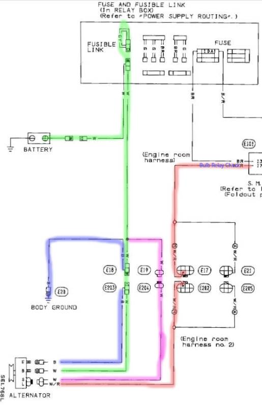
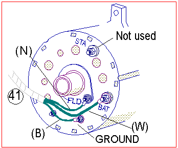
Basic Alternator Wiring

The leftmost of the two spade connectors around the perimeter of the alternator will sometimes be marked 1.
Basic alternator wiring. Ford alternator wiring diagram internal regulator. In any case dynamos became obsolescent over 30 years ago service and parts will be very difficult to find. This current is fed to the cars battery charging it for later use. Plug the alternator connector in the receptacle on the alternator.
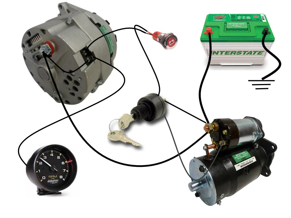
It must be switched or else it will drain the battery overnight. Splice a 14 gauge wire to the smaller pigtail from the connector. This is the field wire that energizes the alternator. It requires advanced knowledge to fix an alternator with this diagram.
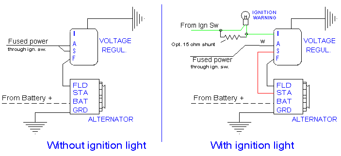
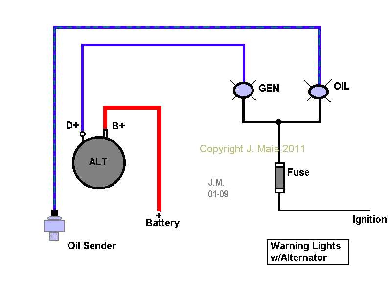
This wire runs to the ign terminal of the ignition switch. Connect a small 12 volt warning light in series in this wire. Without it the alternator wont start charging. The alternator converts the engines mechanical rotations into an electrical current using a pulley and belt system.
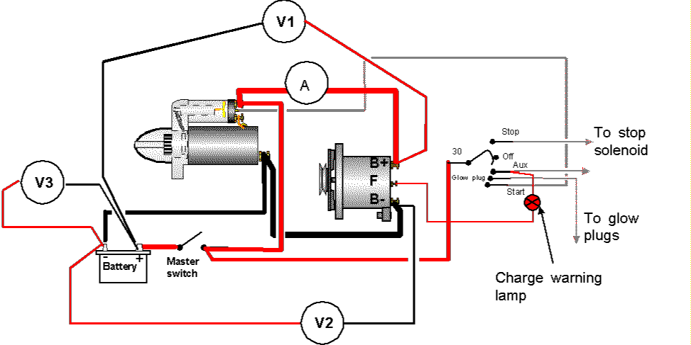
It is usual to wire the alternator to the main. A wiring diagram is a simplified conventional photographic depiction of an electric circuit. Basic alternator wiring there are several basic types of nissan alternator each with their own wiring system. It reveals the elements of the circuit as streamlined shapes and the power and signal links in between the gadgets.
Charging system alternator. Collection of delco 3 wire alternator wiring diagram. In newer models the alternator is internally regulated and can be connected with only one wire linked to the cars battery. It consists of ignition switch fuse panel engine compartment relay box instrument cluster and many more.
This is referred to as a three phase current. Unless one has a very basic boat where the charging system is only used to charge an engine battery for the next start a dynamo is not really up to the job.

