Control Circuit Wiring Diagram

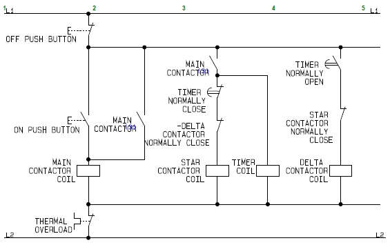
The star delta y d 3 phase motor starting method by automatic star delta starter with timer.
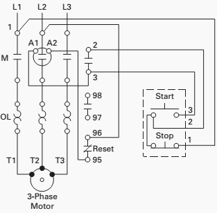
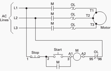
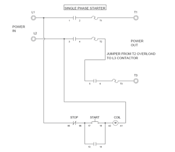
Control circuit wiring diagram. Pete vree 28780 views. Three phase motor connection schematic power and control wiring installation diagrams. See image below for an example of 3 wire control being used to pull in a contactor to start a 3 phase motor. Wiring diagrams show the connections to the controller.
Control circuitsschematic diagrams wiring diagrams and reading schematic diagrams 1. Components used only in special circumstances. When you press the start button and the stop button is not pressed the 24vdc relay energizes and it pulls in the r1 contactor that feeds three phase power to the motor. In this convention the hot and neutral power conductors are drawn as vertical lines near the edges of the page with all loads and switch contacts drawn between those lines like rungs on a ladder.
Wiring diagrams sometimes called main or construction diagrams show the actual connection points for the wires to the components and terminals of the controller. You thus might want to consider using a low drop regulator such as the national semiconductor lm2941ct. Mechanical connection between two components such as those shown in electrical symbols 5 8. I used to suggests these circuit by use principle most pwm pwm control speed motor 12v by tl494 form.
An alternative to the conventional schematic diagram in ac power control systems is the ladder diagram. The most common use of 3 wire control is a startstop control. Field wired or installed components. Factory wired or.
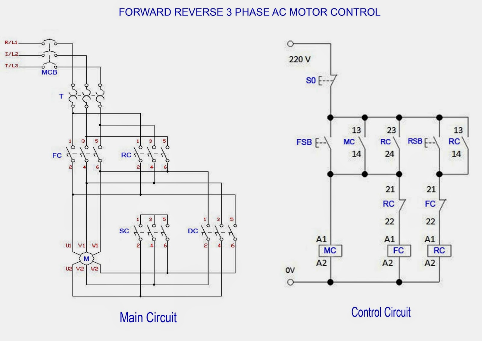
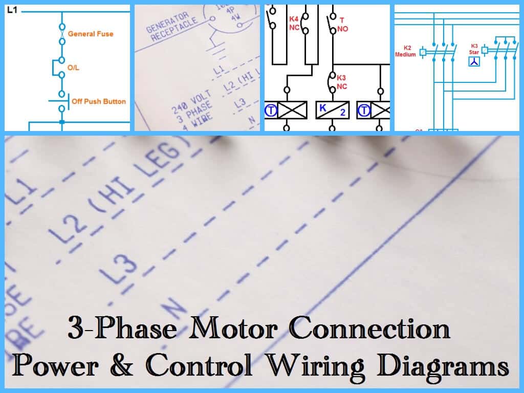
Electric circuit electrical circuits circuit diagram electrical symbols circuit diagrams electrical circuit diagram electrical wiring diagrams motor control circuit diagram star delta wiring diagram star delta control diagram star delta starter circuit diagram star and delta connection delta connection delta connect motor control diagram motor control circuit diagram contactor. Posted by circuit diagram in motor control circuits this is circuit for dimmer a lamp or controll speed of a dc motor. The voltage drop across the regulator is at least 175 v for a motor current of for example 300ma and in any case 2v at the maximum current level of 1 a. Three phase motor connection stardelta y d reverse forward with timer power control diagram.
Ladder diagram basics 3c 3 wire control duration.
