Cs130d Alternator Wiring Diagram

Delco remy cs130 cs121 series alternator repair manual basic operating principles page 2.
Cs130d alternator wiring diagram. How to wire a gm cs130d alternator. All dash lights gauges will function. You may fairly simply exchange the blower motor by by yourself it is not way too challenging. Where the regulator is identified with an i marking on the regulator case the circuit in figure 3a applies.
Ford 6g to 3g part w2740. All lights gauges will function. Cs130 alternator wiring is sense wire needed. I was told to have one wire going to ignition hot and then another going to to a momentary hot with a light in series.
Cs130d alternator wiring diagram cs130d alternator wiring diagram free download wiring diagram if your blower in your furnace isnt doing the job anymore the furnace blower motor could possibly be busted. The advantage of connecting the s sense wire directly to the alternator output is that it measures the output voltage directly and eliminates a bunch of old problematic samurai wiring. Page 1 of 3 1. Use this harness when installing a ford 3g series small or large case alternator in a vehicle with a 6g.
So if it worked on a later model car i cant really be sure that the s wire is required. Wiring instructions for the gm delco remy internally regulated cs130 alternator. Series factory wiring harness to a delco ad244 or cs130d. If this oem wiring is the least bit faulty the alternator output will fluctuate and could easily overcharge the battery.
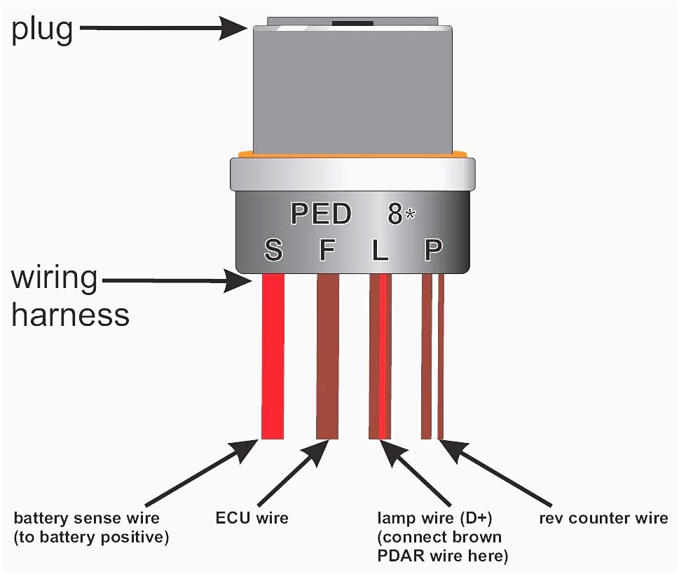
My alternator plug only has two wires l and f terminals. Delco cs130d breakdown c2009 jn auto electric inc. The gm delco remy cs130 alternator was used on gm vehicles from about 1986 1996. I searched and found many threads on the cs130 but not the cs130d.
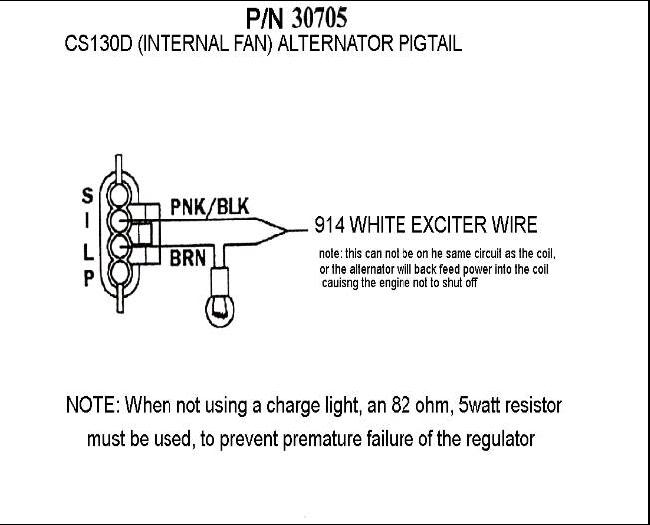
Discussion in electrical systems started by wentworth sep 8 2009. Look at you factory wiring diagram and be sure to bypass the ammetre because its not make to take 105a and on the connector there is sflp you only need to connect the s to the post in back of the alternator and 4ga wire from post to battery and the l to a 12v source on and start and dont forget to install a 82ohm 5 watt resistor or a charging light on that l wire the f and.


