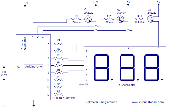
Digital Voltmeter Circuit Schematic Diagram
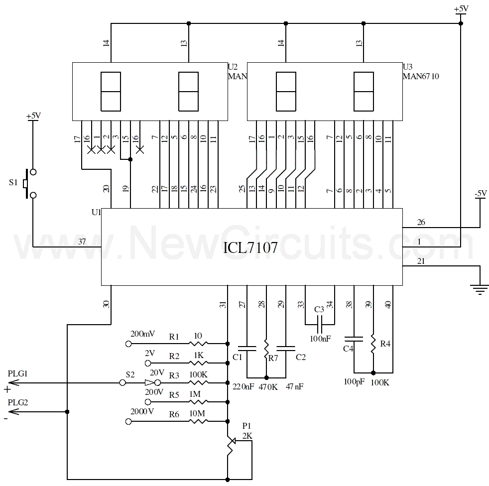
Circuit diagram and working explanation.
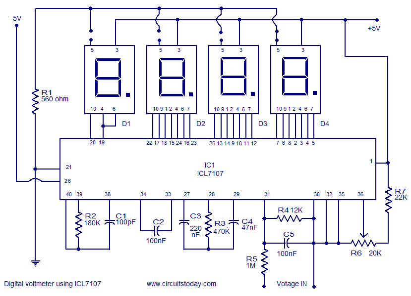
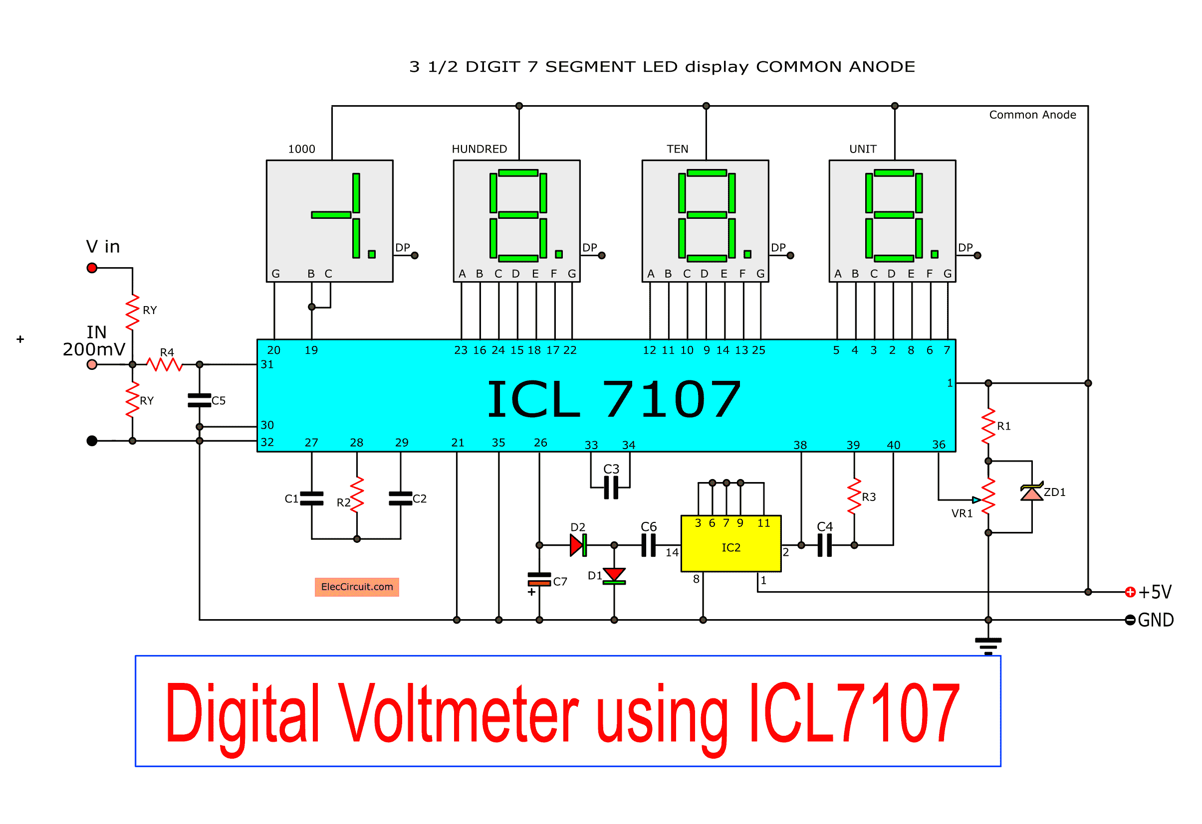
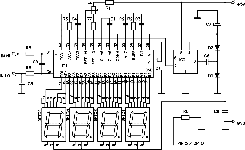
Digital voltmeter circuit schematic diagram. So the display will show in 1888. Try connecting pin 37 pin test with the positive voltage. Of course the easiest way is used as the dc voltage meter circuit. The power supply for this circuit is 5v.
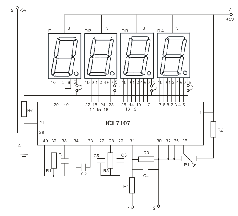
It can be used to measure voltage current and resistance. Here is the schematic diagram of digital dc voltmeter built based ic icl7107. Next adjust vr1 until the voltage at pin 36 is equal to 100 mv. Hence it is required to measure electrical properties of power supplied to appliances or devices.
Instruments used for measuring quantities electrical quantities such as voltage current energy etc are called as meters such as voltmeter ammeter phase sequence meter energy meter and so on. Note that variations in the supply voltage affect the measurement adversely. This circuit will be good to display your power supply output. Powerline voltmeter schematic circuit diagram.
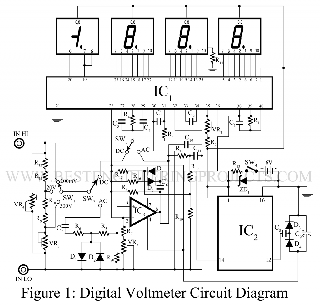
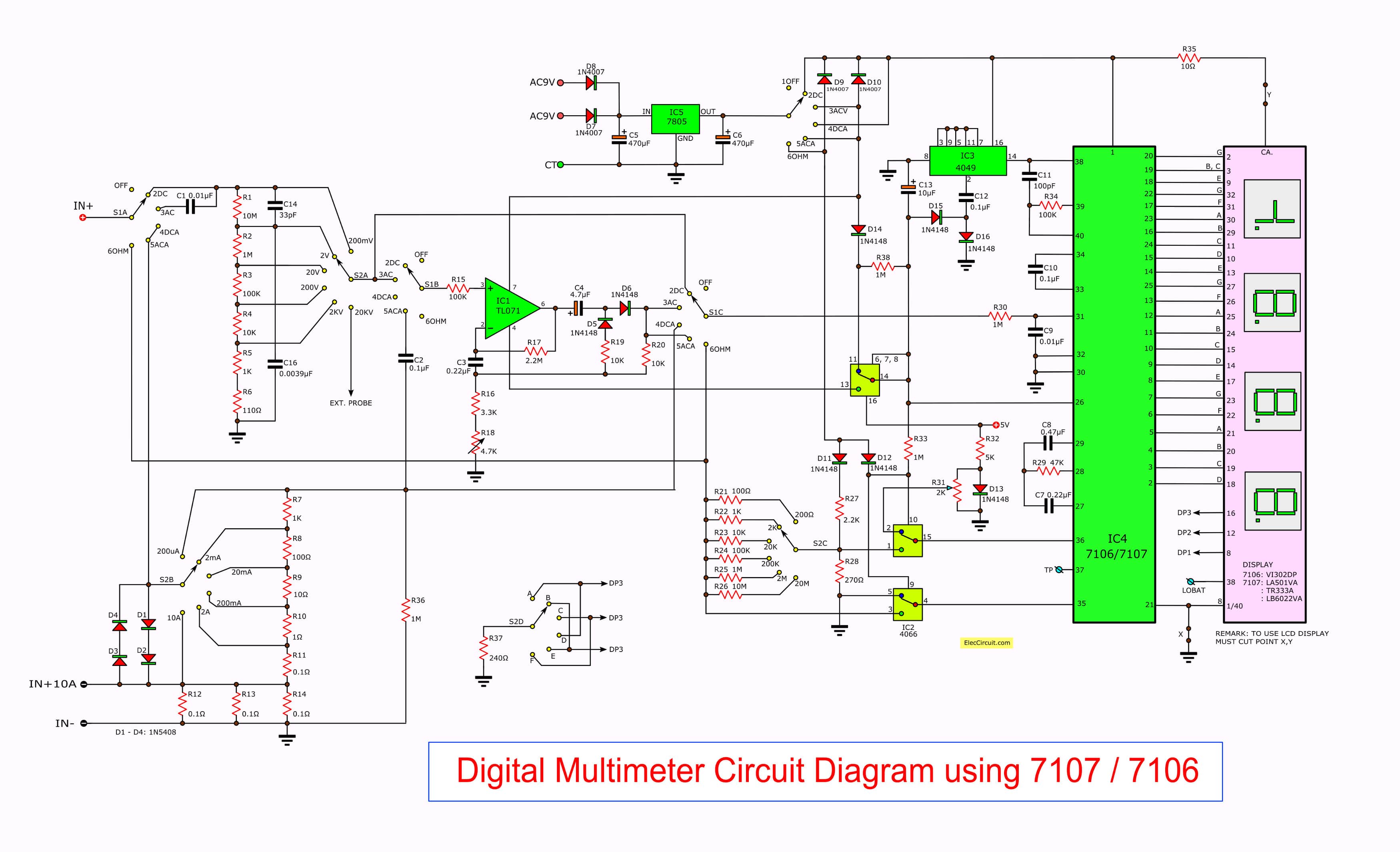
Digital multimeter circuit using icl7107. As circuit is shown in table 1. Analog multimeter shown in the figure is cheap but difficult for beginners to read accurately. Sw converter for digital am car radio schematic circuit diagram.
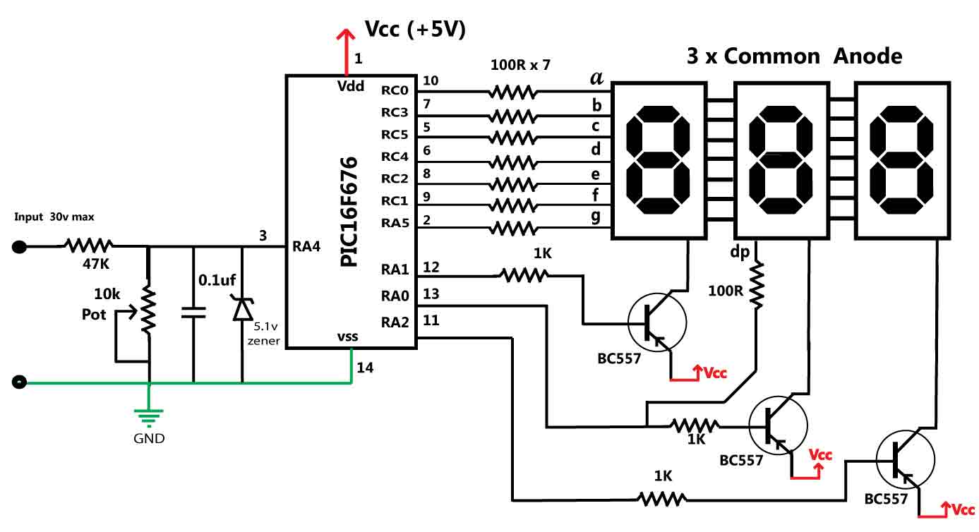
R1 8k2 r2 47k 470k r3 100k r4 2k r5 r6 47k r7 0r 4k7. Digital led voltmeter circuit diagram. We can be applied to measure the voltage range higher. Referring to the circuit diagram below the unit is a full fledged digital voltmeter circuit which can be used for measuring direct voltages right from zero to 199 volts.
When the input is negative the unit leds do not light. Keypad encoder ic with serial output schematic circuit diagram. Next try short circuit at the input number is displayed as. Working of this digital voltmeter circuit is very simple.
The range can be appropriately widened or shortened simply by altering the value of the 1m resistor positioned in series with the input terminal. Multimeter is a measuring instrument. Most modern multimeters are digital. In figure 1 the schematic diagram of this project.
Led digital voltmeter working with circuit diagram. An analog meter figure a moves a needle along a scale. The function of the meter can be changed by switching the dial. Internal adc of this ic reads the voltage that to be measured and compare it with an internal reference voltage and converts that into the digital equivalent.
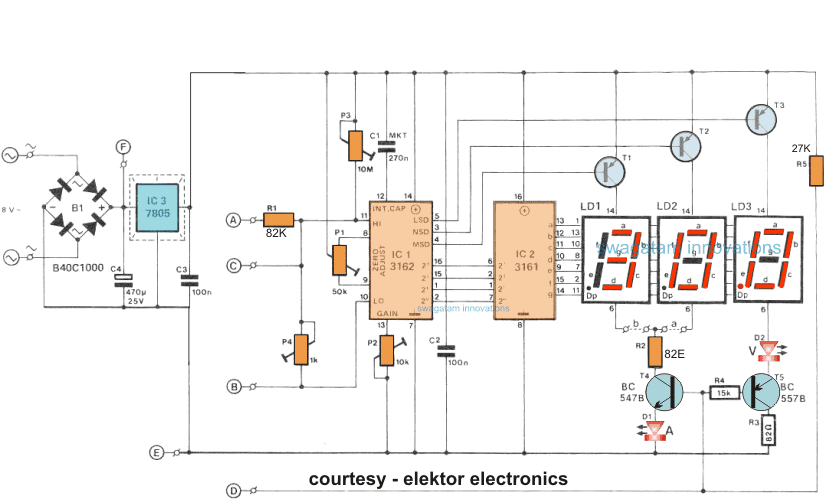
You may use 9v battery and then use regulator ic lm7805 to achieve 5v stabilized voltage. Adc inside the ic is integrating converter or dual type analog to digital converter. The characteristics of the circuit that can measure voltages up to 200mv. It indicates the ic circuit is working correctly.
It is therefore advisable to use a regulated source for instance a 9 v pp3 battery and a type 7805 regulator.

