Flotech Over Fill System Wiring Diagram
A color coded wiring.
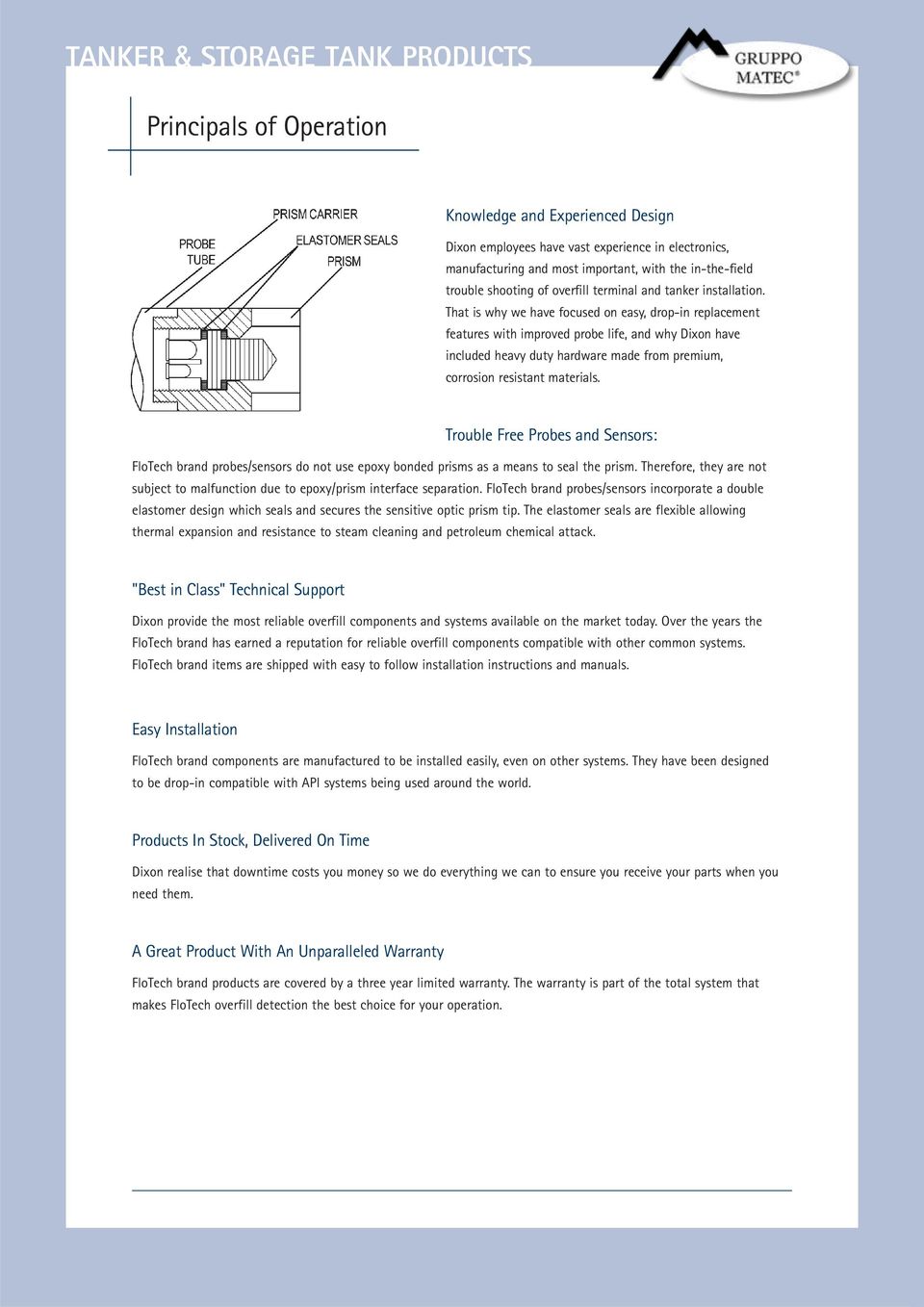
Flotech over fill system wiring diagram. The flotech api optic 5 wire system is a conventionally wired system which requires wiring connections to be made using crimp connectors. The loading rack will also have a reaction time. Once the probe is adjusted to the proper height tighten the clamp screw. Flotech ft404 cable is color coded to ease installation and troubleshooting.
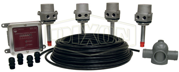
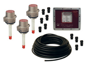
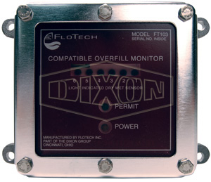
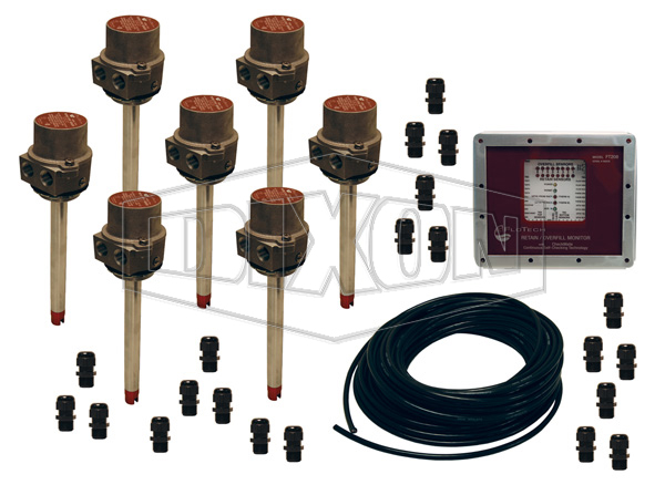
Flotech recommends wiring the sensors to the ft208 monitor using ft404 11 conductor cable for up to 8 compartment systems. Flotech recommends wiring the sensors to the ft208 monitor using ft404 11 conductor cable for up to 8 compartment systems. Construction the sensor housing contains a 5 wire probe in a cast aluminum housing. Flotech ft208 can be wired to work with 2 wire ft151 sensors or api 5 wire ft101 sensors.
The actual sensing point adjustment should be determined by the total response time required to prevent a tank overfill condition. One man wet test feature which signals an audible alarm when sensors are wetted. Tests all api two five wire optic thermooptic systems with up to eight compartments. A color coded wiring schematic is.
The flotech api optic 5 wire probe is electronically and mechanically compatible for drop in replacement of other commonly used 5 wire probes. The flotech sensor reaction time is one half second. Flotech ft404 cable is color coded to ease installation and troubleshooting. Lcd screen displays the final test results and a passfail indication for easy rapid testing of the overfill system.
Complete wiring schematic is shown in back of this booklet.
