Fuel Gauge Schematic
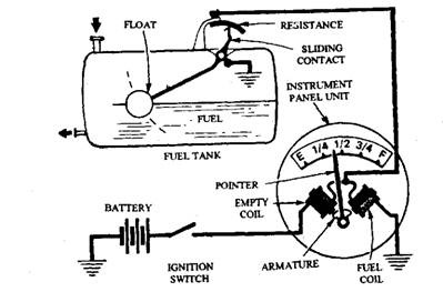
Fuel Gauges Automobile
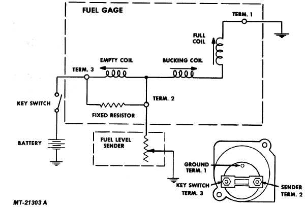
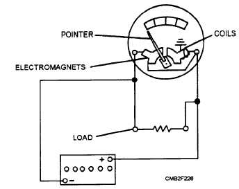
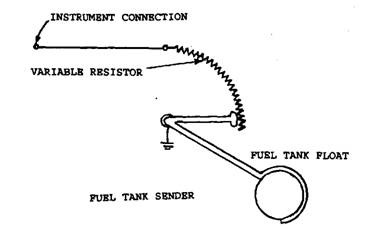
Fig 17 Fuel Gauge Circuit Diagram
How To Test And Replace Your Fuel Gauge And Sending Unit

Electric fuel sender wiring diagram wire center wiring diagram.
Fuel gauge schematic. Adding any auto meter gauge to your vehicle will help to ensure accurate and consistent readings from your car or truck. Checking boat fuel gauges and fuel sending units. Gasoline is extremely flammable. A wiring diagram is a simplified standard pictorial depiction of an electrical circuit.
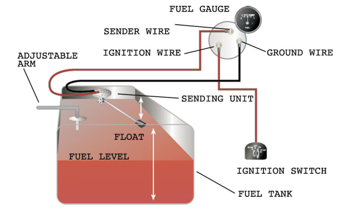
Wire a fuel gauge by first disconnecting the old dysfunctional unit to replace it with a new one. Keep tank area free from sparks and flames. Next connect a wire from the float on the fuel tank to the negative terminal of the fuel gauge. Gauge and sending unit wiring diagram and industry recommendations.
It shows the parts of the circuit as simplified shapes and the power as well as signal links between the devices. Obtain 12 volt power from the fuse box using a standard wire and connect it to the positive terminal of the fuel gauge. Use a special fuel gauge resistor to protect the original 6 volt fuel gauge that will be running in a 12 volt system. Connect ground wire to 14 fasson terminal on sender.
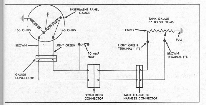
Variety of marine fuel gauge wiring diagram. Automotive wiring diagram worksheet inspirationa fuel gauge sending. All gm fuel gauges from the early 1930s to the 1960s operate on a 30 ohm scale. How to wire auto meter fuel gauges by brandy alexander.
How to determine if your boats fuel gauge or fuel gauge sending unit is bad. Over the years auto meter has established itself as a manufacturer of quality professional automotive gauges. Install the new gauge reconnect the wiring and turn on the power. Installing an auto meter fuel gauge is an easy task once.
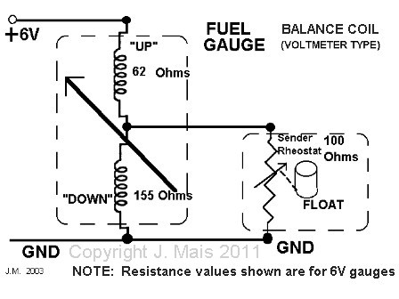
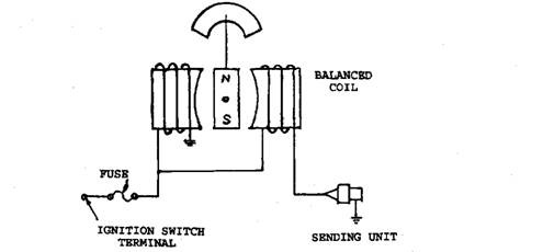
It is a very sensitive gauge and the windings will be damaged by 12 volts. Fuel gauge check the wiring diagram that comes with the kit and mark the back of the new fuel gauge with symbols for each post. S for the sender g or for the ground and i for the ignition. Empty tank of fuel and fumes before continuing with installation.

Fuel Gauge Schematic Schematics Online
Fuel Gauges Automobile

Wiring Diagram Fuel Gauge Wiring Diagram

Fuel Gauge Wiring Diagram 1 Wiring Diagram Source

57 Chevy Fuel Gauge Wiring Wiring Diagram
Fuel Gauge
Chevy Fuel Gauge Wiring Wiring Diagrams

Sw Em Fuel Gauge
Scooter Fuel Gauge Wiring Diagram Wiring Schematic Diagram

Fuel Gauge Test Schematic 63 67 Willcox Corvette
Fuel Gauges Automobile
Fuel Gauge Schematic Wiring Diagram Content
Boat Fuel Sender Wiring Gauge Schematics Online

Gauge Wiring Diagram Catalogue Of Schemas

Fuel Level Gauge Schematic Schematics Online

Ford F 150 Fuel Gauge Wiring Diagram Technical Diagrams

How To Install A Moeller Fuel Gauge
Fuel Gauges Automobile
