Garmin Echo 70 Wiring Diagram

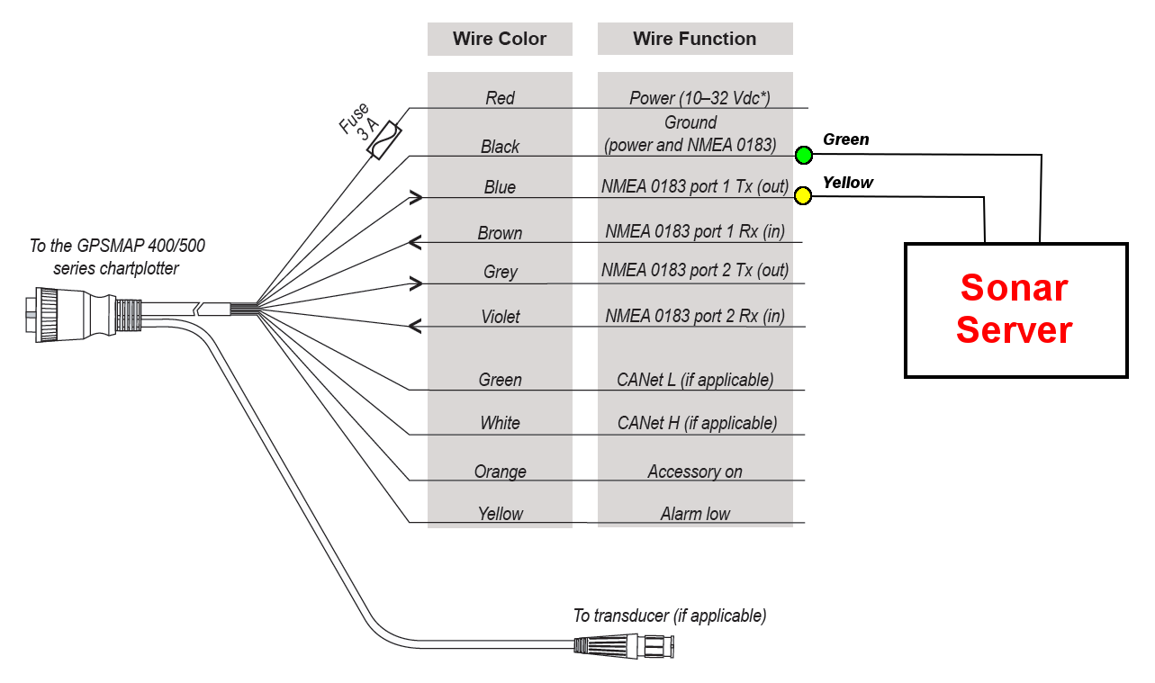
The wiring harness connects the device to power and nmea 0183 devices.
Garmin echo 70 wiring diagram. 2 if necessary extend the wires using 082 mm 2 18 awg or larger wire. Echomap 5070 series installation instructions important safety information warning. This feature is not available on echomap plus 7090. 3 connect the red wire to the positive terminal on the battery or fuse block and connect the black wire to the negative terminal.
Installation recommended from your garmin dealer. Sets the device to transmit waypoint names or numbers via nmea 0183 while navigating. If you experience difficulty during the installation contact garmin product support. Sharing your garmin quickdraw contours maps with the garmin quickdraw community using garmin connect.
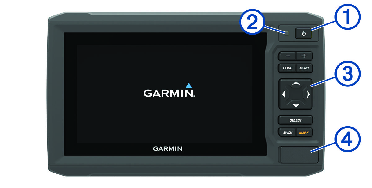
Item wire function wire color a nmea 0183 internal port rx in brown a nmea 0183 internal port tx out blue a ground power and nmea 0183 black a power red connecting to a garmin device to share user data note. User data sharing cable wiring diagram user data sharing cable wiring diagram. Assigning a shortcut key. Echomap plus 7090 front view.
About the wiring harness the wiring harness connects the device to power nmea 0183 devices and a lamp or a horn for visible or audible. 2 if necessary extend the wires using 82 mm2 18 awg or larger wire. Using numbers may resolve compatibility issues with older nmea 0183 autopilots. Restores the nmea 0183 settings to the original factory defaults.
The device has one internal nmea 0183 port that is used to connect to nmea 0183 compliant devices. Wiring to power 1 route the power cable from the swivel mount to the boat battery or fuse block. You can get the latest owners manual and translations of manuals from the web. Displays nmea 0183 diagnostic information.
If it is necessary to extend the power and ground wires you must use 082 mm 2 18 awg or larger wire. Echomap 7090 series installation instructions to obtain the best performance and to avoid damage to your boat install the device according to these instructions. 3 connect the red wire to the positive terminal on the battery or fuse block and connect the black wire to the negative terminal.


