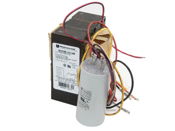
Hid Ballast Wiring Diagram 480
Before installation make certain supply and ballast voltages are compatible.
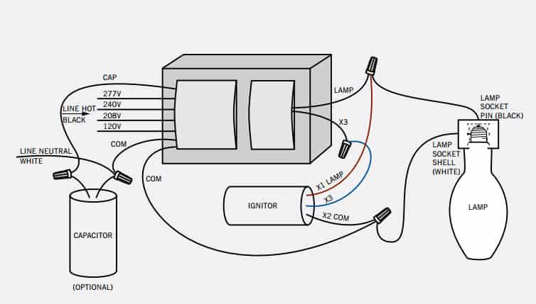
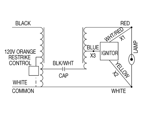
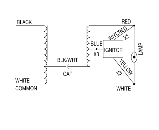
Hid ballast wiring diagram 480. Hid ballast wiring diagrams ballast wiring diagrams for hid ballast kits including metal halide and high pressure sodium lighting ballasts. It reveals the components of the circuit as simplified shapes as well as the power and also signal connections in between the devices. Our advance 71a6051 metal halide 400w ballast 480v is a great solution for you lighting needs. Field wiring connections should only be made by qualified personnel.
Most magnetic hid ballasts are multi tap meaning they can be connected to several different voltages. The multi 5 line takes the popular quad ballast design 120 208 240 and 277 volts and adds 480 volt capability. Here we display wiring diagrams for metal halide probe start mercury vapor ballast and high pressure. Photo control wiring diagram 208v 240v 277v 480v blk red line line photo control wht lampload red or wht blk blk yel compact fluorescent ballast wiring diagrams 1 1 lamp 2 2 lamp quad volt ballasts are factory wired for 277v input.
The universal precise family of products offers these innovations. Hid ballast wiring connections typical hx high reactance ballast connections for hi hx ballasts with model number 5xx suffix such as m0100 71c 511 1. Assortment of 277 volt ballast wiring diagram. Wiring diagrams and more dynamic cross reference tool find equivalent philips advance products for 24 different manufacturers.
Ballast label quick id lamp ballast label quick id wiring diagram replacement capacitor ratings replacement ignitor ratings 1 888 geballast for quick answers ge hid lamp ballast kits are packed in double corrugated packaging with inner support to withstand the tough handling and potential mistakes that can happen on the job. Click now and buy today. Looking for a reliable hid or metal halide ballast at a good price. A wiring diagram is a simplified standard pictorial representation of an electric circuit.
12 hid ballast kits 15 grainger regional point of contact. 1 or 2 347 480 f54t5ho centium 120 119 035 025 100 1 or 2 hcn2s5490cwl 2lmw5.


