Interlock Wiring Diagram
What Is Electrical Interlocking Power Control Diagrams
What Is Electrical Interlocking Power Control Diagrams
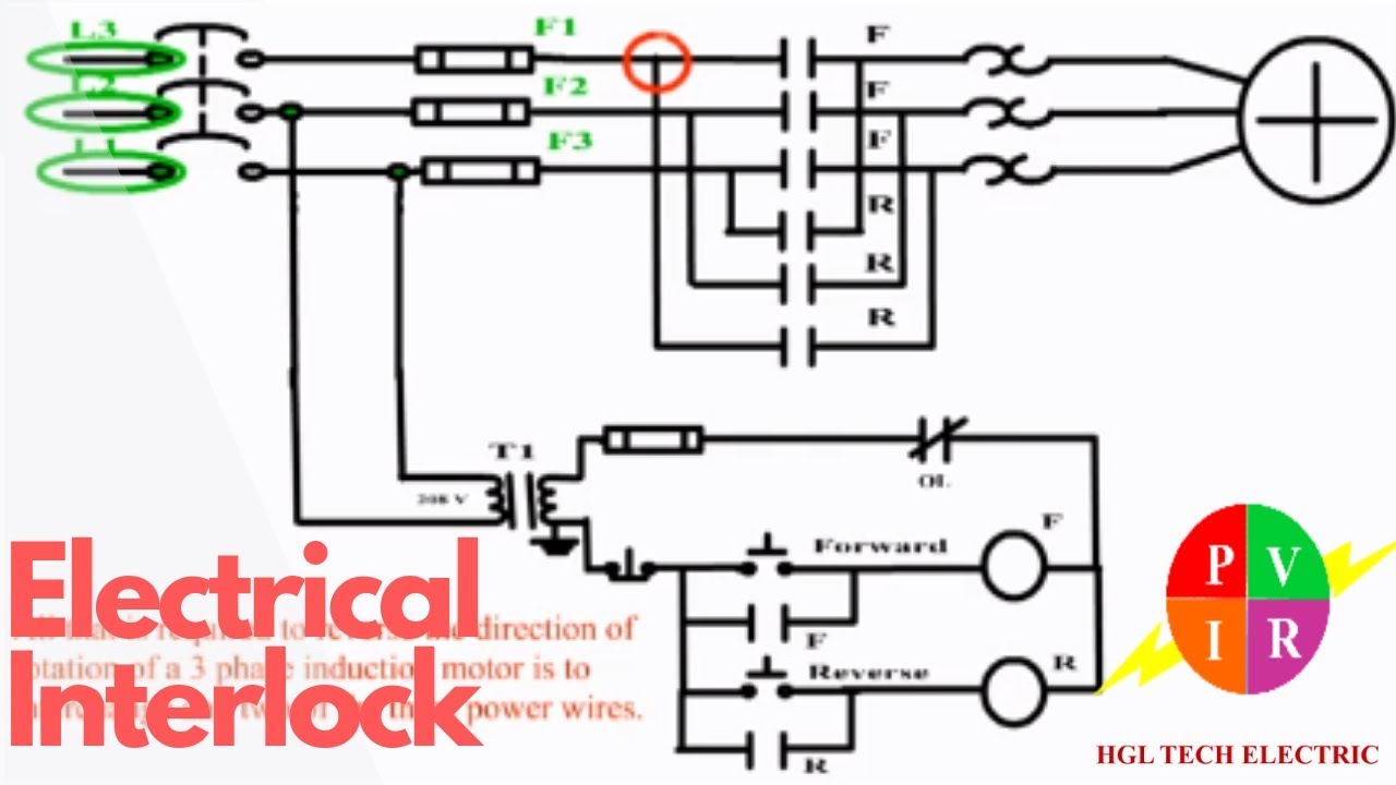
Electrical Interlock Motor Control Forward Reverse Forward Reverse Circuit Diagram

How it works.
Interlock wiring diagram. Once the interlock relay receives power and latches it feeds into the power in relay coil to turn on the rest of the control panel. Assortment of ignition interlock wiring diagram. Once latched power for. Collection of ignition interlock wiring diagram.
A wiring diagram is a simplified traditional pictorial representation of an electric circuit. Collection of intoxalock wiring diagram. Two door entry with dt 7 first man in option wiring diagram 12. Two door entry with day timer wiring diagram 08.
It reveals the parts of the circuit as simplified shapes as well as the power and signal links between the devices. Two door interlock normally locked wiring diagram 11. A wiring diagram is an easy visual representation with the physical connections and physical layout of your electrical system or circuit. Two door entry hard code used to turn user code on and off wiring diagram 23.
A wiring diagram is a streamlined conventional photographic representation of an electric circuit. A wiring diagram is a streamlined conventional pictorial representation of an electrical circuit. It reveals the elements of the circuit as streamlined shapes as well as the power and signal connections in between the tools. It reveals the elements of the circuit as streamlined shapes and also the power as well as signal links between the devices.
A wiring diagram is a simplified traditional pictorial representation of an electrical circuit. It reveals the elements of the circuit as streamlined forms and the power and also signal links between the gadgets. The safe start interlock relay only receives power when the power key switch is set to on and all three other switches are set to off. Two door interlock normally unlocked wiring diagram 13.
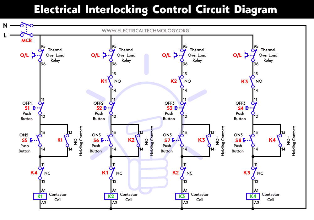
Two door system wiring diagrams. In short we may change the motors operation and control by doing some modification in the above simple electrical interlocking control circuit diagram. For example if we need that motor 1 should stop when motor 3 starts to run then we may use a normally close nc link of m3 in line 1. Interlock wiring diagram what is a wiring diagram.

Smart Start Ignition Interlock Wiring Diagram Wiring

8 Electrical Wiring Diagram For The Controller Box Of The
How To Bypass An Ignition Interlock Device How To Bypass An
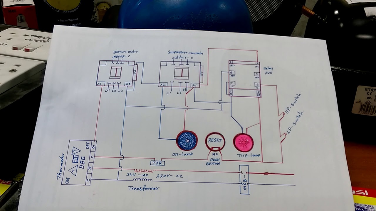
Hvac System Interlock Wiring Diagram In Hindi Youtube
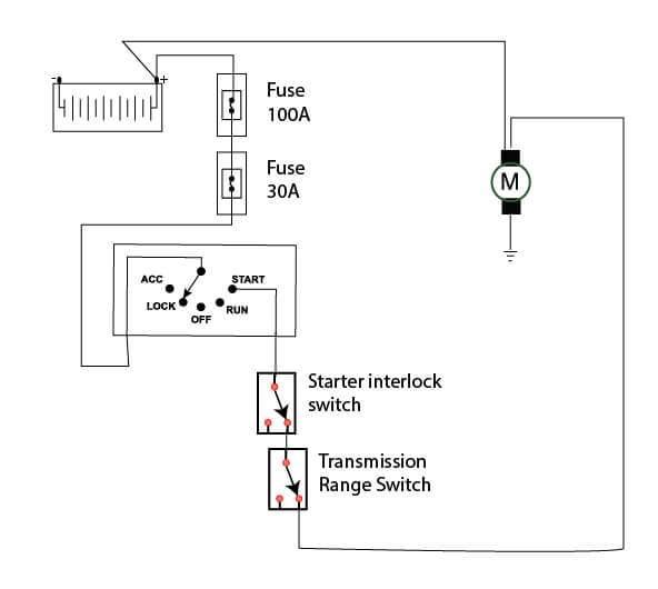
Mazda Starter Wiring Diagram Ricks Free Auto Repair Advice

Repair Guides
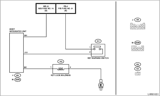
Subaru Legacy Service Manual Dtc B1015 Key Interlock
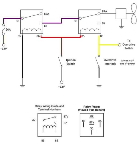
Electric Fan Cycling Solution Moss Motoring

Wiring Diagram For Interlock Transfer Switch Electrical

Electric Vehicle Conversion Control And Interlocks

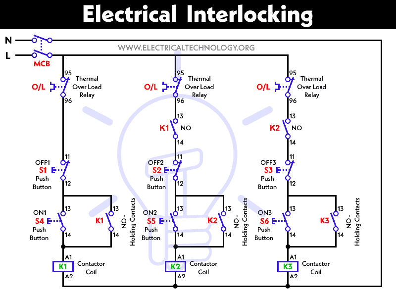
Basic Interlocking Of Electrical Circuit Sparkyhelp

Repair Guides
Interlocking Wiring Diagram Wiring Resources

Interlocking Wiring Diagram Wiring Schematic Diagram

Plc Implementation Of Forward Reverse Motor Circuit With

Smart Start Inc Rgb Color Model Ignition Interlock Device

Battery Drain Should Interlock Unit Fuse Have Constant Power

All Wiring Diagram Contactor Interlock Wiring Diagram
