Johnson Outboard Tach Wiring Diagram

Visit the post for more.
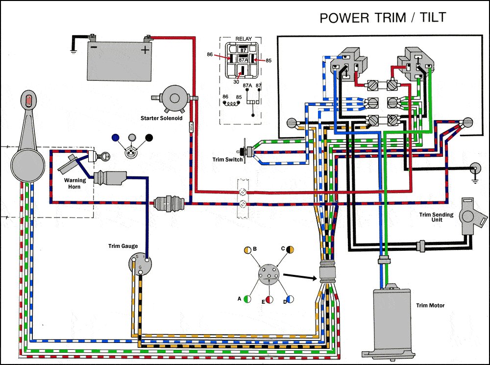
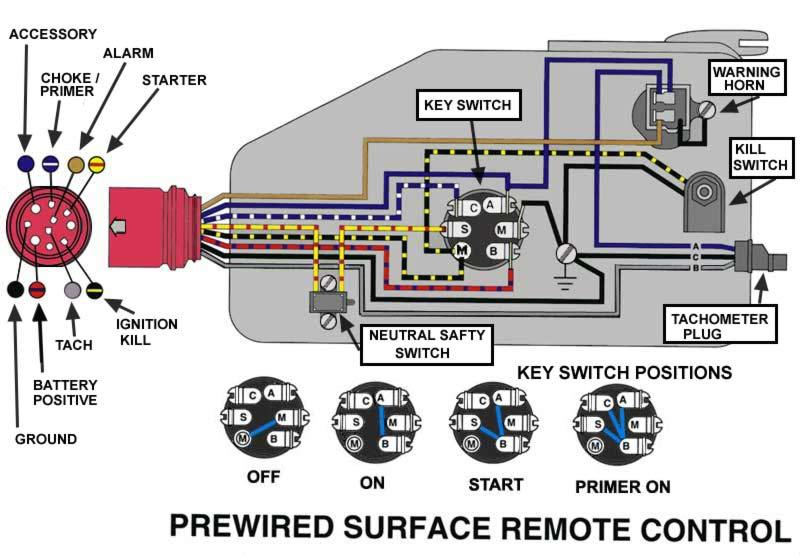
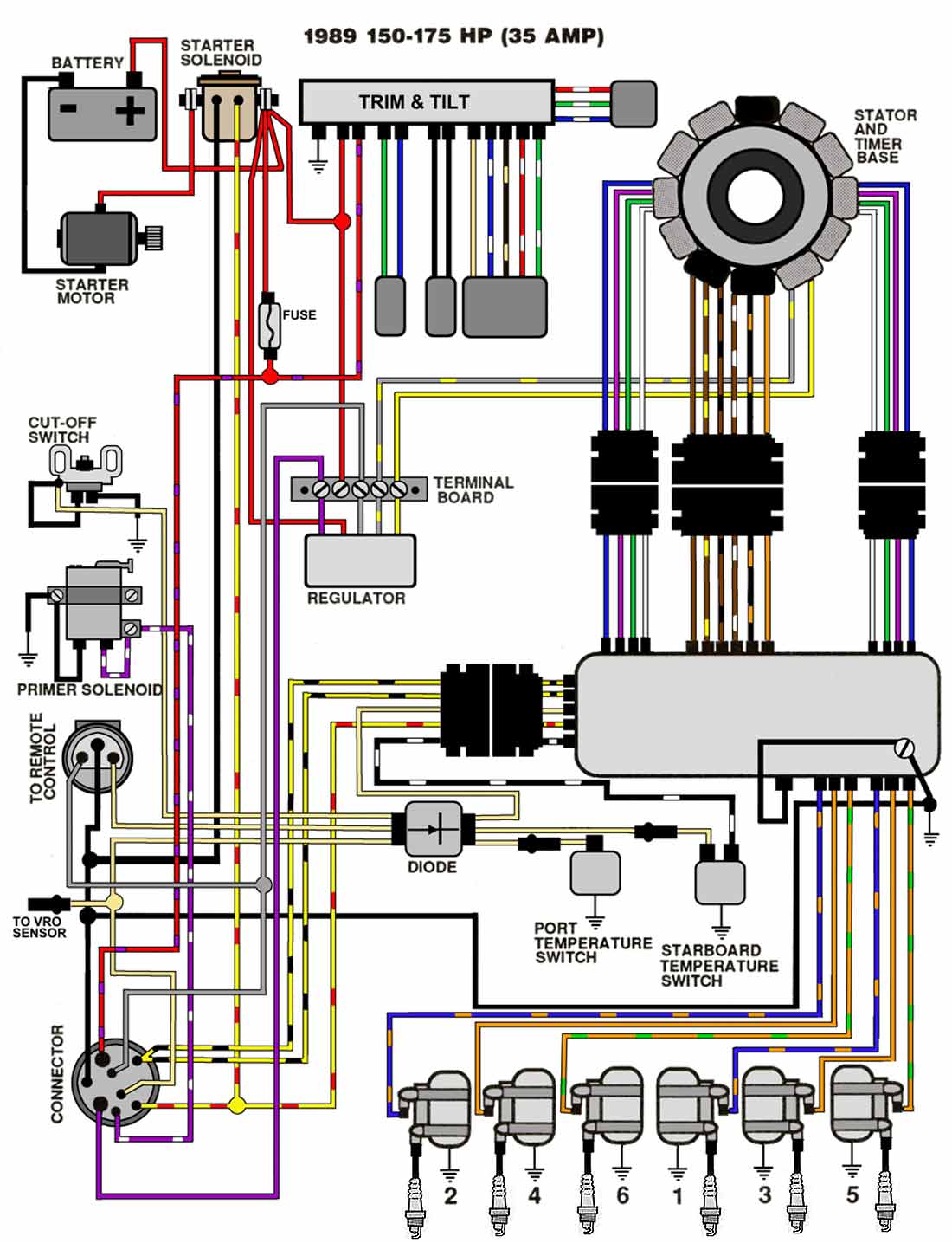
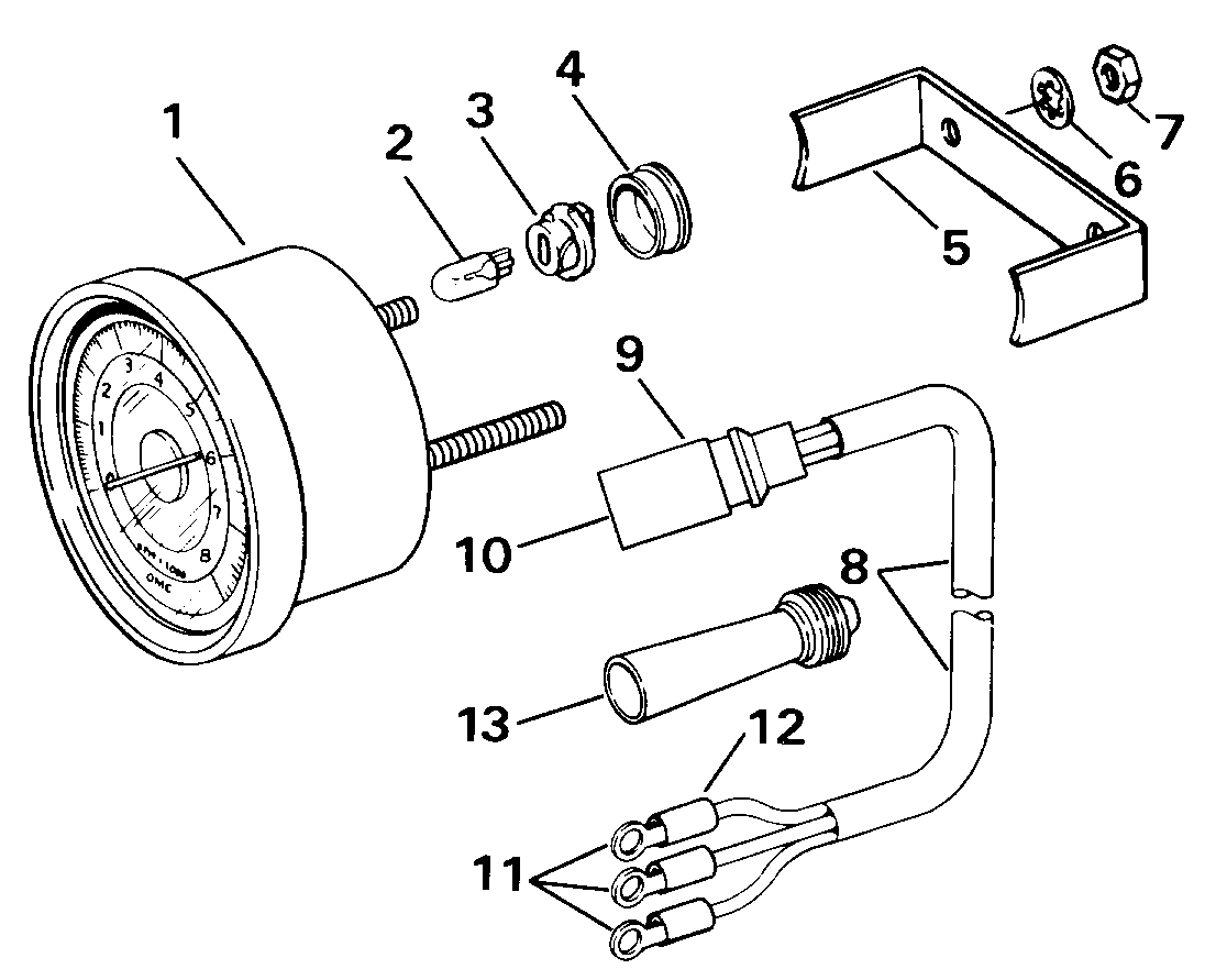
Johnson outboard tach wiring diagram. How to install a tach on an evinrude boat motor. Wiring color codes here is a listing of common color codes for evinrude and johnson outboard motors. The generated tachometer signal is the gray wire that comes out of the emm and goes to the 8 pin connector at the tach. Outboard engine wiring series links.
For instance 99 hp to 15 hp 4 stroke engines manufactured after 2001 are set for six poles. The wiring basics of connecting a tachometer rpm gauge to an outboard motor. Your tech can check the continuity of the wire and if there is the proper frequency signal coming from the emm using the evinrude diagnsotic software. These codes apply to later model motors approximately early 80s to present.
This sets the correct pole position for your engine. Mastertech marine evinrude johnson outboard wiring diagrams with 1998 evinrude wiring diagram by admin through the thousand photos on line concerning 1998 evinrude wiring diagram picks the top series along with greatest resolution exclusively for you and this pictures is actually among photographs selections in this very best graphics gallery regarding 1998 evinrude wiring diagram. In this video i install an tachometer in my boat. Depress and turn the small selector switch on the back of the tachometer with a screwdriver.
If the number of poles is not known consult the outboard tachometer application chart or call faria marine instruments at 860 848 9271 with make model hp and year of the motor. This is the tachometer i used http. I wire up the power and then select the number of pulse or cycles my outboard has to get the correct reading. 1996 evinrude 40hp parts used in this test.
Outboard motor control wiring part 1. For connectorized cases be sure.


