Ladder Diagram Application
In manual control when the motor can be started in either fast or slow and latches in until the timer times out.
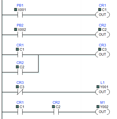
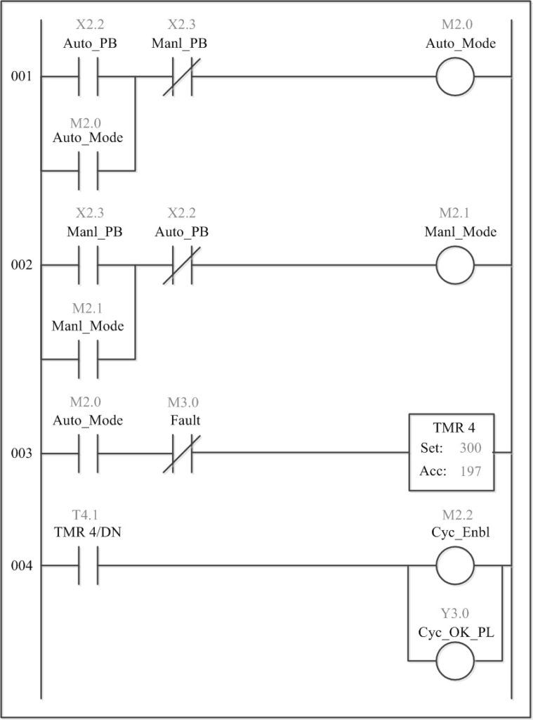
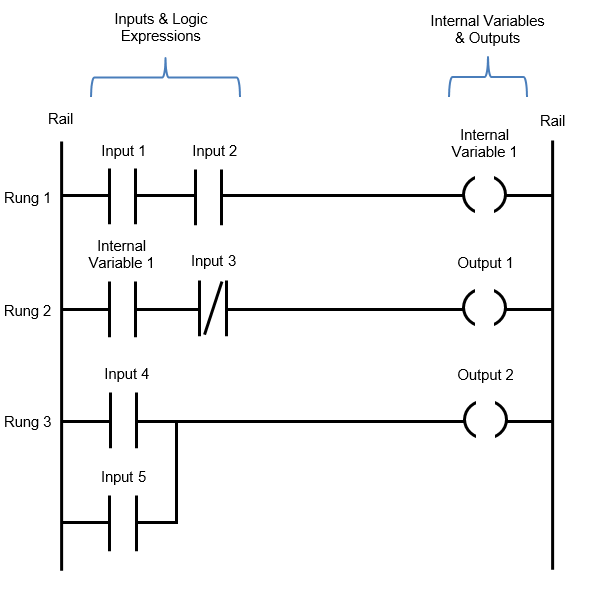
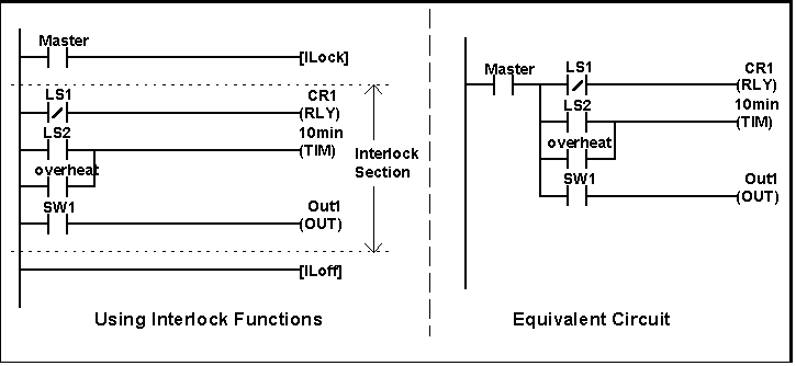
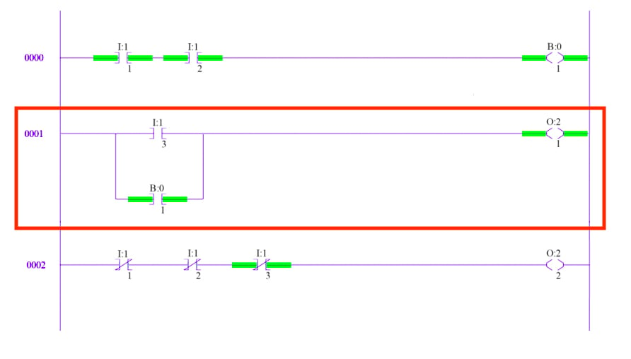
Ladder diagram application. While explaining by mistake i named it as power trails. Ladder logic has evolved into a programming language that represents a program by a graphical diagram based on the circuit diagrams of relay logic hardware. You can used plc ladder simulator to create ladder logic diagrams using components from the standard set used in these diagrams. Ladder diagram for motor control.
Plc ladder simulator is a simulator for the android operating system with input and output objects that simulate the io ports of a real plc. Lets take a look. The many similarities between the ladder diagrams used to program plcs and. Star delta plc ladder diagram.
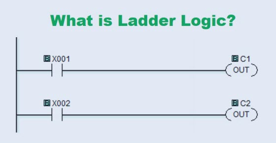
Ideal for engineering students unlock full featured course with 250 video lectures at 2 slideshare uses cookies to improve functionality and performance and to provide you with relevant advertising. Important in the video there are two vertical straight lines of ladder diagram called as power rails. Ladder logic was designed to have the same look and feel as electrical ladder diagrams but with ladder logic the physical contacts and coils are replaced with memory bits. Ladder logic is used to develop software for programmable logic controllers plcs used in industrial control applications.
Here we considered temperature control application. One of the most common ways to start an ac motor is by first starting the motor in star connection. Write plc program using ladder diagram language for this application. Similarities with ladder diagrams.
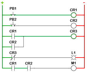
For this program the relay logics ladder diagram is duplicated with ladder logic. In fact the plc is a common choice for controlling ac motors. Lets look at a simple example. Split range concept mostly used when single controller is used to control multiple final control elements.
Just about any industrial process that has electrical controls andor instrumentation would benefit from the application of a programmable logic controller for monitoring control and automation. For this type of application we need to use split range concept. Timed out the motor runs fast for 5 min. After watching this video you will.
A customer asked for a ladder diagram for one motor and two contactors fastslow with auto control where the motor runs for 2 min. Here are some examples of ladder diagrams for motor control. When a plc is used primarily to replace relays timers and counters its hard to beat the simplicity and usefulness of ladder diagram programmingtheir ability to accept programming in ladder diagram format is one of the reasons for the success of programmable logic controllers plcs in the industry. This presentation has various plc projects with ladder logic examples.
Motor control can be done with a plc program.
