P Id Logic Diagram

P Id Logic Diagram Wiring Schematic Diagram 33 Glamfizz De
The Op Amp Pid Controller
The Op Amp Pid Controller
These elements mechanical equipment piping piping components valves equipment drivers and instrumentation and controls are represented by symbols and labels.
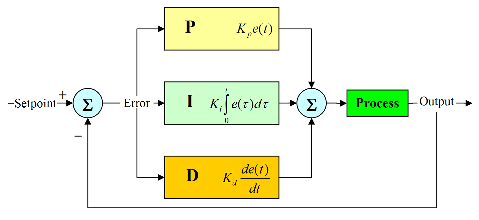
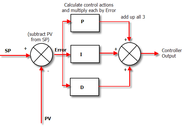
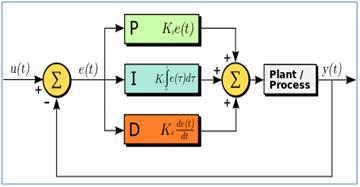
P id logic diagram. Piping and instrumentation diagram documentation criteria april 2008. Here is a diagram that explains this click to see full size. Pid controller block diagram by wikimedia. Here i have tried to explain pid and pefs an easy way.
Pip pic001 4 and. Pids can seem mysterious but dont have to stay that way thanks to our intuitive pid software. This article discusses the common symbols used on logic diagrams. The pid algorithm controls the output to the control point so that a setpoint is achieved.
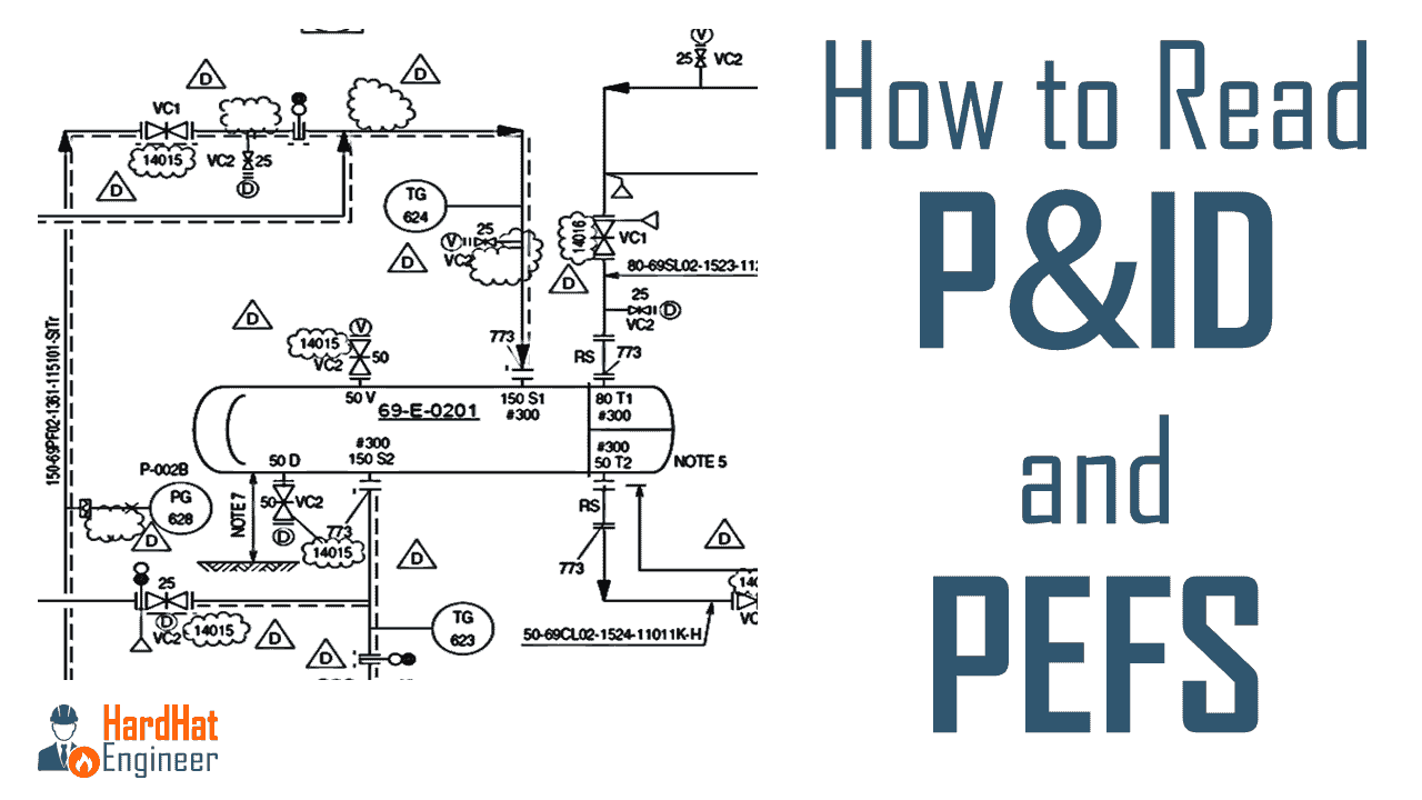
The piping and instrument diagram pid based on the process flow diagram pfd represents the technical realization of a process by means of graphical symbols for equipment and piping as well as graphical symbols for process measurement and control functions. A piping and instrumentation diagram pid is defined by the institute of instrumentation and control as follows. Its quick easy and completely. Pid is more complex than of pfd and includes lots of details.
Isa 52 binary logic diagrams for process operations. You will learn how to read pid and pefs with the help of the actual plant drawing. Pid proportional integral derivative controller is a control loop mechanism. Top level diagram contains an object for each pid and child pages then provide a graphical list of the relevant loop and logic diagrams which are then diagrams under each object.
Programmable logic controllers also have the inbuilt pid controller instructions. This practice applies to all diagrams that fit the definition of a pid in section 3. A diagram which shows the interconnection of process equipment and the instrumentation used to control the process. And their respective control schemes in relation to the elements of the plant and its interconnection pipes.
Due to the flexibility and reliability of the pid controllers these are traditionally used in process control applications. Ch 19 pid block 1 chapter 19 programming the pid algorithm introduction the pid algorithm is used to control an analog process having a single control point and a single feedback signal. 12 min read want to make a pid of your own. A pid is a diagram that shows condensed information from multiple specialties.
To read and interpret logic diagrams the reader must understand what each of the specialized symbols represent. The use of logic symbology results in a diagram that allows the user to determine the operation of a given component or system as the various input signals change. In the process industry a standard set of symbols is used to prepare drawings of processes.
Ideal Pid Controller Using Active Circuit Realization Youspice

Block Diagram Of Combination Fuzzy Pid Logic Control At
Pid For Dummies Control Solutions

Logical Diagram Of Fuzzy Logic And Pid Controller
How Does A Pid Controller Work Structure Tuning Methods

Pid Controller Wikipedia

Pid Controller Wiring Diagrams Wiring Diagram Library
Learn How To Read P Id Drawings A Complete Guide

A New Adaptive Configuration Of Pid Type Fuzzy Logic
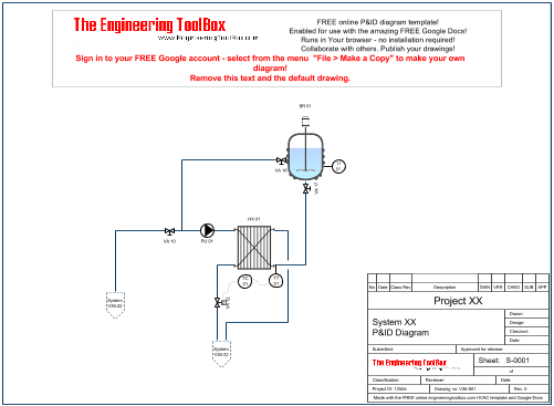
P Id Diagram Online Drawing Tool

How To Program A Basic Pid Loop In Controllogix Realpars
Advanced Pid Algorithm Pid And Fuzzy Logic Toolkit

P Id Logic Diagram Wiring Library

Figure 4 From D6114 Diesel Engine Speed Control A Case

Online Tuning Of Fuzzy Logic Controller Using Kalman

Schematic Of Control Strategy For Ac Load Bus Inverter 2 4

P Id Diagram Basics Part 3 Functional Identification And

Fuzzy Logic Regulate Temperature Humidity And Cooling For
