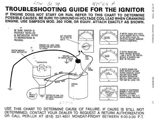
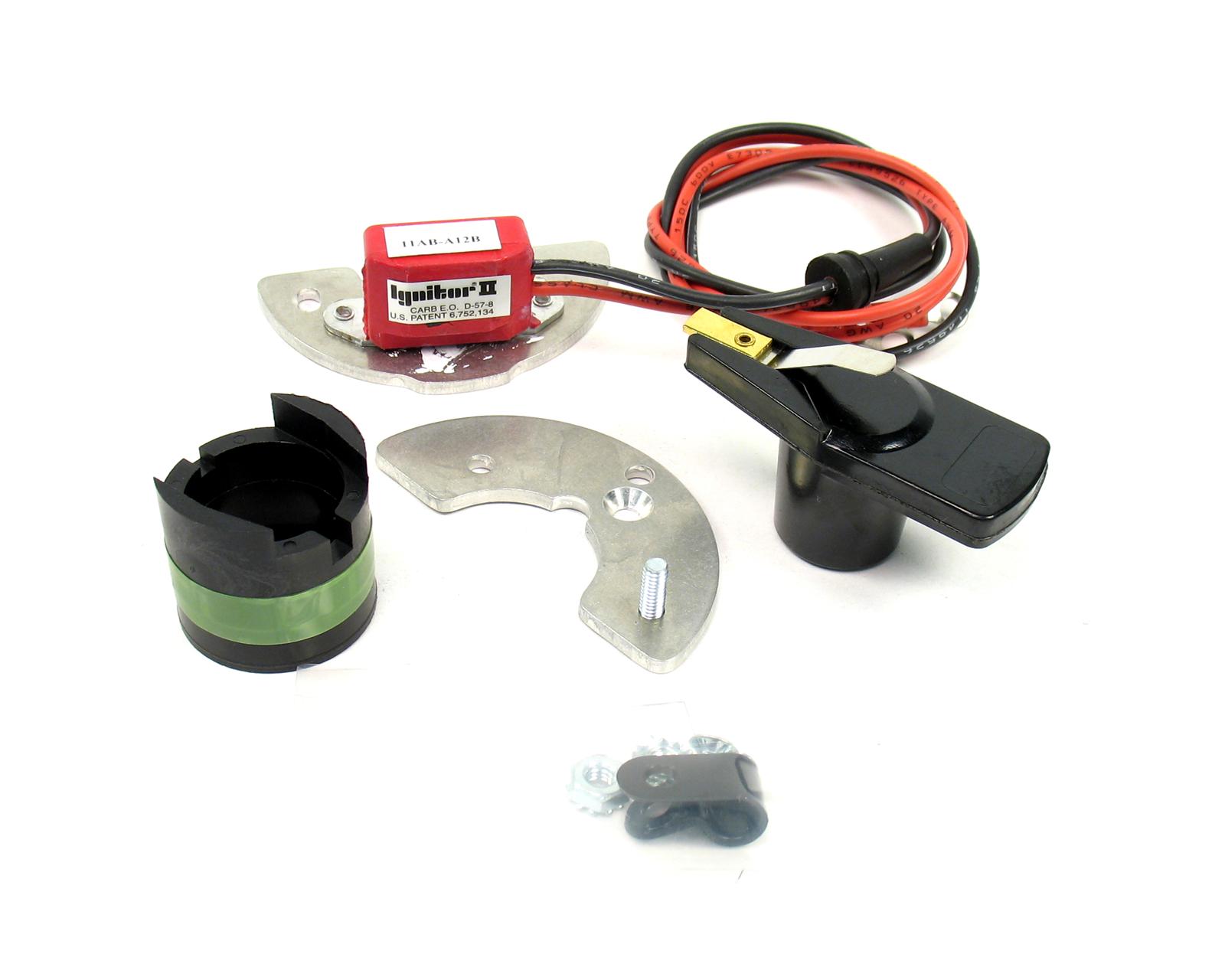
Pertronix Ignitor Wiring Diagram Triumph
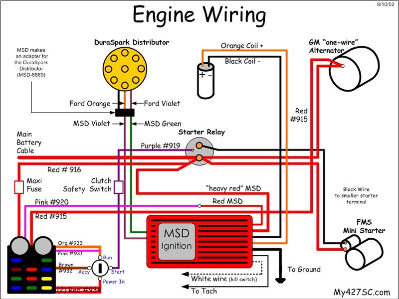
Pertronix ignitor wiring diagram.
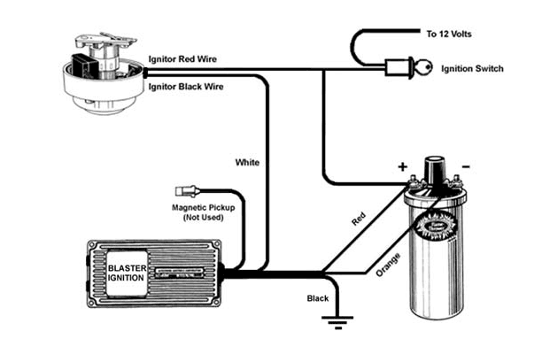
Pertronix ignitor wiring diagram triumph. If not the arrangement will not function as it ought to be. Pertronix ignitor wiring diagram triumph manual e books pertronix ignitor wiring diagram uploaded by bismillah on thursday february 14th 2019 in category uncategorized. Read and follow the wiring diagram. The information and tips that have been elaborated above ought to be a great kick start however.
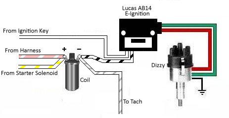
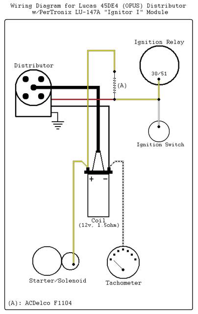
50 of all pertronix failures i see are from something that got missed. This is a pertronix electronic ignition kit for a mgb 1976 to 1980 spitfire 1975 to 1980 midget 1500 1975 to 1979 and tr7 1975 to 1980 with lucas distributor not delco unit. The wiring diagram shown below is modeled after one obtained from pertronix. If your car has been converted from positive earth to negative earth recheck every single step of the conversion before proceeding with the installation.
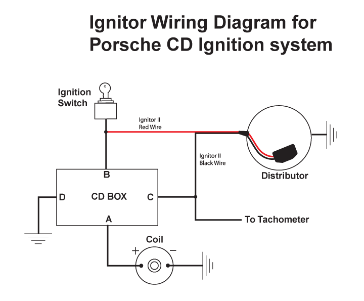
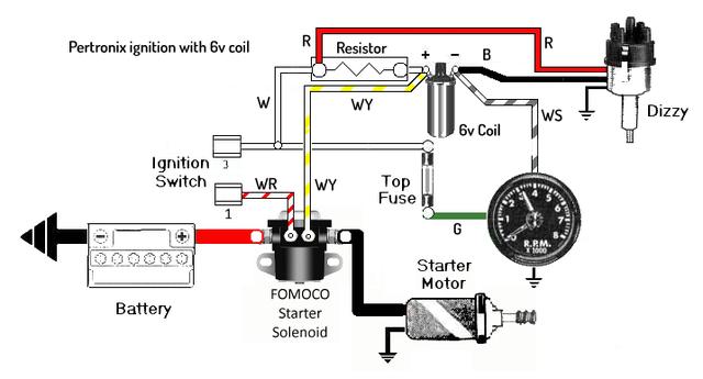
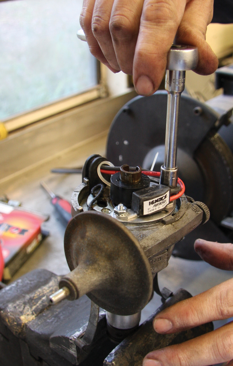
It goes without saying that this is valid only for cars without ballast resistors viz our t series cars. Cam and jeff give tips and tricks on pertronix 1 2 and 3. Ignitor common questions and answers figure 1 wiring diagram conventional points system with ballast resistor figure 2 wiring diagram ignitor system without ballast resistor figure 3 wiring diagram ignitor system with ballast resistor note. These kits are very easy to install and are truly set once and forget it i.
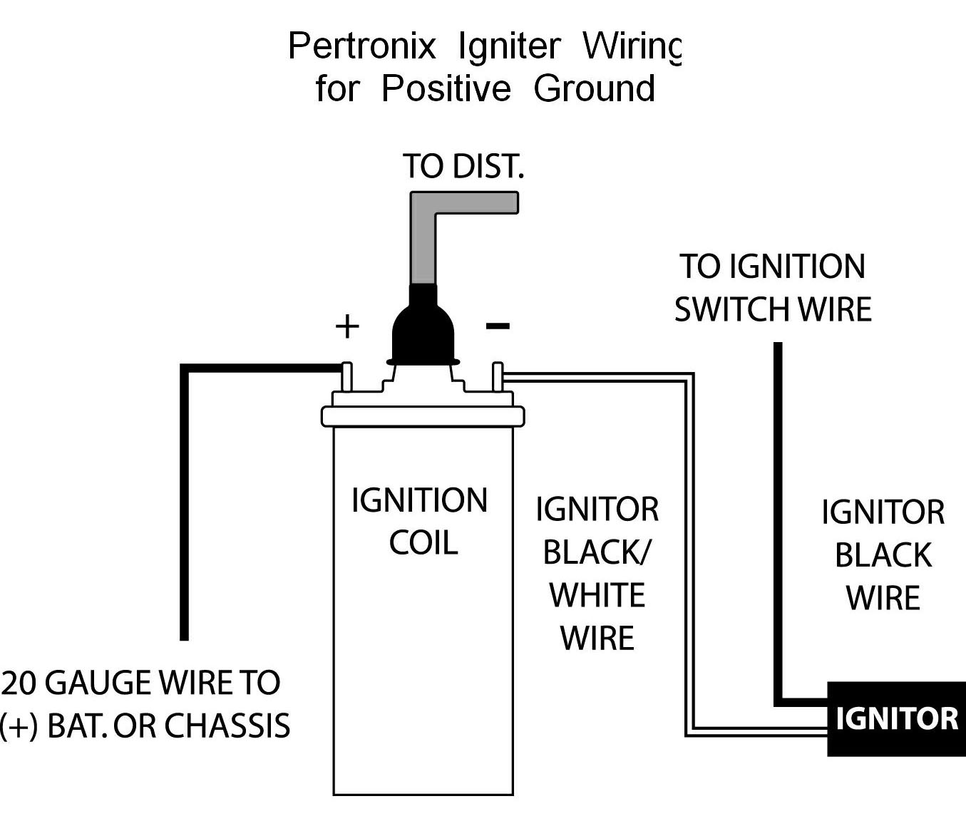
Pertronix igniter wiring for negative ground cars. Pertronix igniter wiring for positive ground cars. Each component ought to be placed and linked to different parts in particular manner. We show how to install the pertonix ignitor i pertonix ignitor ii and pertronix ignitor iii.
Pertronix ignitor wiring diagram pertronix ignition wiring diagram pertronix ignitor ii wiring diagram pertronix ignitor iii wiring diagram every electrical arrangement is made up of various different components. This shows the proper hookup for a pertronix igniter in a car wired for negative ground or earth if you prefer.
