R 485 Diagram

Rs 232 Rs 485 Rs 422 Communications Specifications
Uart Communication Between Pic32mx795f512l Pc Via Rs485

Rs 485 Wiring Diagram Schematics Online
Rs232 pinout rs232 pinout standards exist for both db9 and db25 connectors as shown below.
R 485 diagram. Rs 485 also known as tia 485 a eia 485 is a standard defining the electrical characteristics of drivers and receivers for use in serial communications systems. The device for which the data is intended responds if necessary. Db25 signal db9 definition 1 protective ground 2 txd 3 transmitted data 3 rxd 2 received data. Rs 485 transmits digital information between multiple locations.
Figures 3 and 4 show an rs485 pinout diagrams for 9 pin db9 and 25 pin db25 connectors. If you use more modules along the network you need to remove the 120 ohm resistors r7 on those intermediate modules. Check the data sheet schematic or block diagram. Two switches are set for 2w or to the 2 wire rs 485 mode.
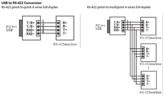
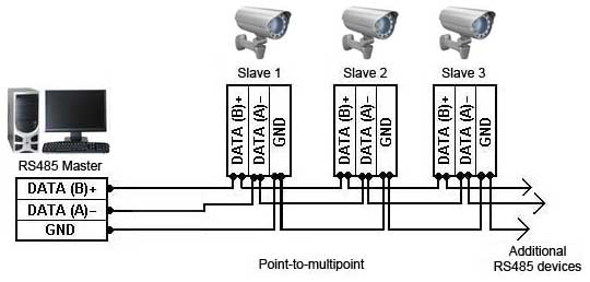
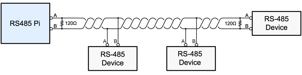
Figure 3 applies to most bb rs 485 converters or serial cards that can be set for 2 wire or 4 wire operation and for some 2 wire converters that use the same circuit board for the rs 422 model. What they are called what information they carry and even the connectors and pin numbers to use. Sl sl sl sl ma twisted pair daisy chain a typical controlsoft rs 485 network all devices on the network receive any transmitted data. A wiring diagram is a streamlined traditional pictorial representation of an electric circuit.
It supports distance of 10 meters for 30 35 mbps and 1200. See the example rs485 network diagram scroll down. Data acquisition articles rs485. Rs485 is primarily used in multi drop configurations that make use of its balanced differential interface.
The standard is jointly published by the telecommunications industry association and electronic industries alliance tiaeia. As displayed in the rs485 cable pinout the interface has all signals in differential configurations. Rs422 and rs485 by contrast define only the electrical characteristics of the driver. The distance and the data rate with which rs 485 can be successfully used depend a great deal on.
Due to differential signals distance carried by signals are more. Variety of rs485 wiring diagram. The following diagram shows the preferred topology of controlsoft rs 485 networks. It reveals the parts of the circuit as simplified shapes and the power as well as signal links in between the gadgets.
Tx and tx carry transmit data and rx and rx carry receive data. Electrical signaling is balanced and multipoint systems are supported. Understanding rs485 and rs422. Rs 485 is designed to transmit this information over significant lengths and 1000 meters are well within its capability.
Rs485 interface figure describes rs485 pin diagram for 9 pin connector. Data rates can be up to and sometimes greater than 10mbps. The 20k resistors hold a known signal when no one is transmitting.

Rs485 Multi Master Communication Circuit Circuit Related
.aspx)
Modbus 485 Wiring Schematics Online

Rs485 Cable Diagram Wiring Diagram Schematics
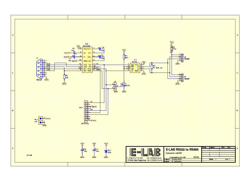
E Lab Rs232 To Rs485 Converter Sch Service Manual Download
Rs 422 Cable Wiring Diagram Technical Diagrams
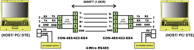
4 Wire Rs485 4 Wire Rs422 Converter Converters

Ltc2873 Rs485 Rs232 Multiprotocol Transceivers Analog

Rs485 Rj45 Wiring Diagram Wiring Diagrams Folder

On The Drawing Board Using Rs 485 Transceivers
Rs 485 Wiring Diagram Catalogue Of Schemas

Cross Platform Rs485 Communication Using C Xanthium
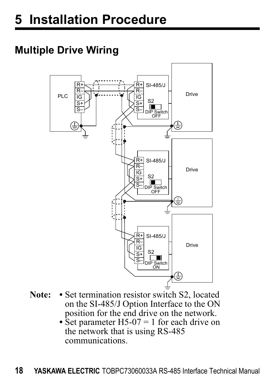
5 Installation Procedure Multiple Drive Wiring Yaskawa Rs
Rs485 Cable Diagram Wiring Diagrams Folder

R 485 Watchmaker Create Your Watch Face

Rs 485 Wikipedia

Usb To Db9 Serial Pinout Wiring Diagram Schematics Online

Rs 485 Wikipedia

Rs485 Cable Diagram Wiring Diagram Schematics
