Solar Circuit Diagram
Presented here is the circuit of a solar light that is bright enough to illuminate a garden while not requiring any wiring to the grid supply and thus lowering the electricity bill.
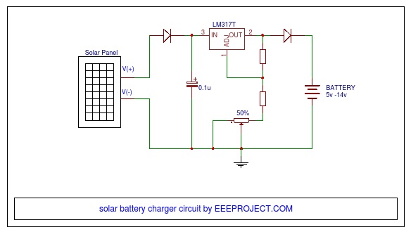
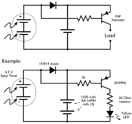
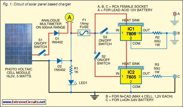
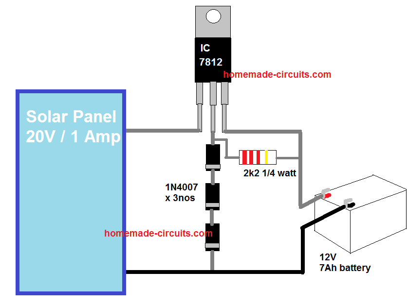
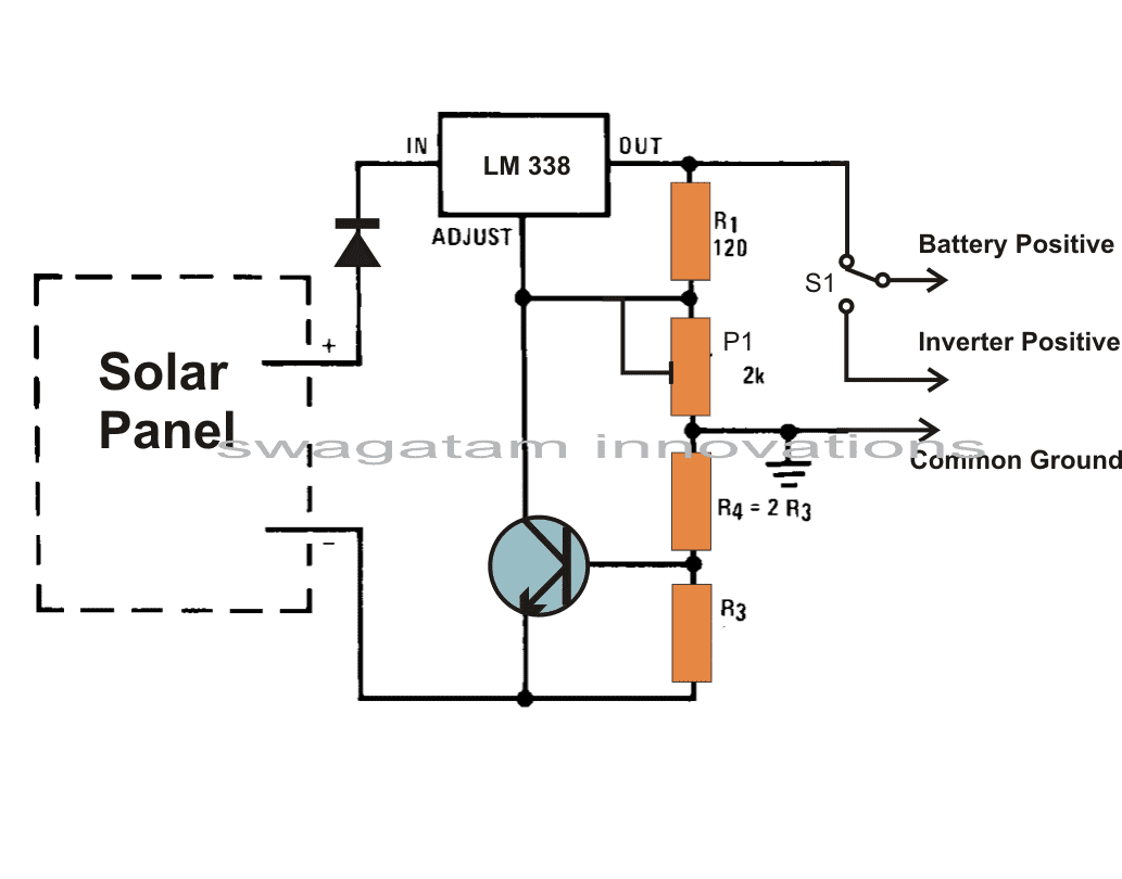
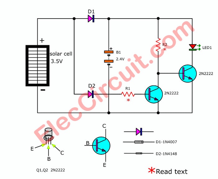
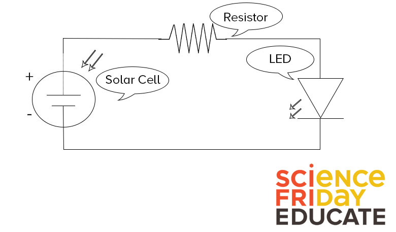
Solar circuit diagram. Circuit diagram of solar panel battery charger step 9. The circuit diagram shows below the solar cells in series their accumulative voltage. Pv solar inverter circuit diagram. N3 to n6 gates are employed as buffers so that the circuit is not dependent on load.
Series parallel wiring sixteen panel solar system. This is a great amount of power. Circuit diagram of solar panel battery charger step 10. Watts since we connected four groups of four panels together in series and parallel this solar system will output 1008w of power per hour maximum under optimal sunlight conditions.
Continuously changing voltage from the buffer phase is useful to the bottom of the current amplifier transistors t1 t2. All about solar panel wiring installation diagrams. Read also circuit diagram of soft starters for induction motors. Circuit diagram of the solar garden light is shown in fig.
Solar panel wiring diagram 6usage and limitations. It carries out the key role of providing square waves to the inverter division. Inverter circuit gives alternating current ac output from battery power source but the battery requires constant dc supply to get charge so the every inverter circuit contains rectifier and battery charger segment. Solar inverter circuit diagram.


