Start Stop Wiring Diagram
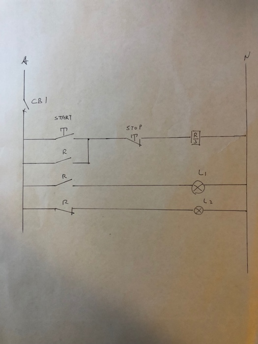
Two Wire Three Wire Motor Control Circuit Motor Control

Two Wire Three Wire Motor Control Circuit Motor Control

Control Wiring 3 Wire Control Start Stop Circuit

Control Wiring 3 Wire Control Start Stop Circuit

3 Wire Start Stop Wiring Diagram Elec Eng World In 2019

3 Wire Start Stop Wiring Diagram Elec Eng World In 2019

3 Wire Start Stop Wiring Diagram Elec Eng World In 2019

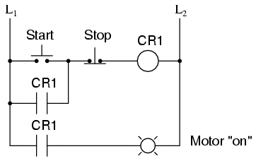
See image below for an example of 3 wire control being used to pull in a contactor to start a 3 phase motor.

Start stop wiring diagram. 2 4 6 m 1 ol 3 phase motor a1 a2 remove wire c when it is supplied. 1 termi nal on the remote pilot device and the termi nal 96 on the overload relay. When you press the start button and the stop button is not pressed the 24vdc relay energizes and it pulls in the r1 contactor that feeds three phase power to the motor. C i m nc.

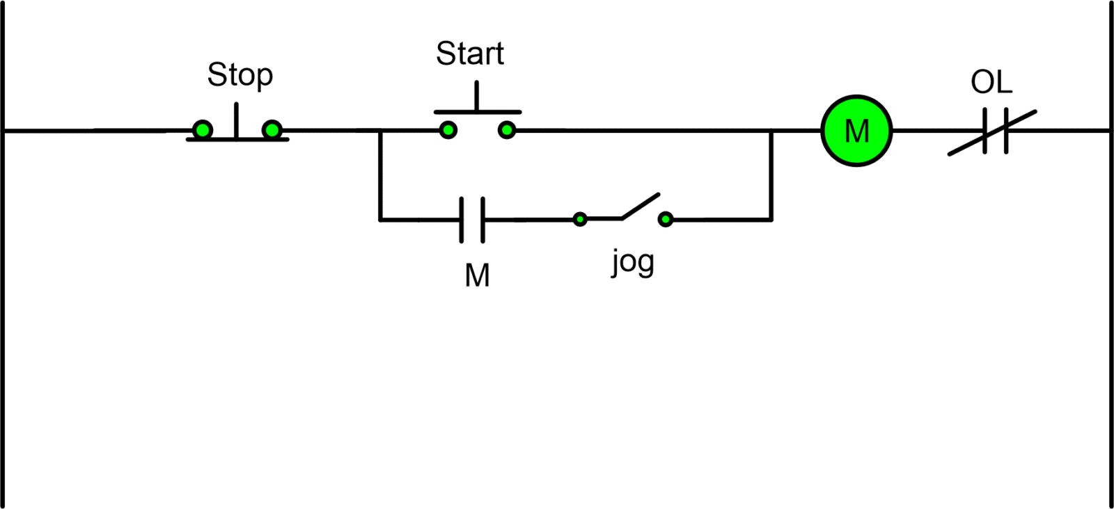
In figure 14 the wires on each side of the m con. The jog when pushed will break the sealing contact and then make a bypass of the start pushbutton. Ladder diagram basics 4 multiple stop start stations. This will keep the m coil on as long as the jog button is pressed.

This video builds on the standard 3 wire circuit by incorporating multiple stopstart stations. Connect separate control lines to the no. The most common use of 3 wire control is a startstop control. Pilot light l2 4 2 3 pilot light start stop bulletin 1495 normally closed auxiliary contacts are required.

Connection diagrams or wiring diagrams show the components of the control circuit in a semblance of their actual physical locations. Start stop 3 2 1 1 3 not for use with auto reset ol relays. The start stop push button station is shown more as an actual device in the control circuit wired to a set of contacts marked 2 and 3. 3 wire circuit by incorporating.

Typical wiring diagrams for push button control stations 7 start stop control wiring diagrams single station with motor stopped pilot light l1 start l2 i 1 stop 2 oi 3 n wol. Remote pilot devices 2 wire control 3 wire control.
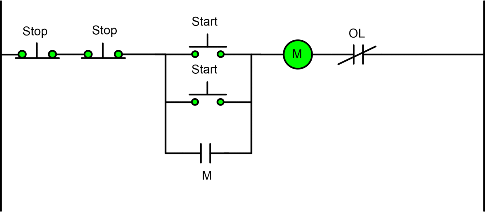
A Three Wire Start Stop Circuit With Multiple Start Stop

A Three Wire Start Stop Circuit With Multiple Start Stop

Start Stop Jog Circuit Motor Control Circuit Diagram

Start Stop Jog Circuit Motor Control Circuit Diagram

Practical Machinist Largest Manufacturing Technology Forum

Practical Machinist Largest Manufacturing Technology Forum

946927 109 D Starter Wiring Diagram With Start Stop And E

946927 109 D Starter Wiring Diagram With Start Stop And E

Wiring Diagram Single Motor With Start Stop Switch

Wiring Diagram Single Motor With Start Stop Switch

Dont Know How To Wire A Start Stop Switch To Motor

Dont Know How To Wire A Start Stop Switch To Motor

Contactor Wiring Guide For 3 Phase Motor With Circuit

Contactor Wiring Guide For 3 Phase Motor With Circuit

How To Wire A Start Stop Station Controlling A 120 Volt

How To Wire A Start Stop Station Controlling A 120 Volt

Three Wire Control Circuit

Three Wire Control Circuit

Multiple Push Button Stations Three Wire Control Multiple Stations Circuit Diagram Start Stop

Multiple Push Button Stations Three Wire Control Multiple Stations Circuit Diagram Start Stop

Practical Machinist Largest Manufacturing Technology Forum

Practical Machinist Largest Manufacturing Technology Forum

Start Stop Switch Wiring Diagram Wiring Schematic Diagram

Start Stop Switch Wiring Diagram Wiring Schematic Diagram

1 Pole Contactor Wiring Diagram Wiring Resources

1 Pole Contactor Wiring Diagram Wiring Resources

Start Stop Contactor Wiring Diagram Wiring Diagram

Start Stop Contactor Wiring Diagram Wiring Diagram

Start Stop Contactor Wiring Diagram Wiring Diagram

Start Stop Contactor Wiring Diagram Wiring Diagram

3 Phase Auto Starter Wiring Diagram Wiring Library

3 Phase Auto Starter Wiring Diagram Wiring Library

Latch Circuits Worksheet Digital Circuits

Latch Circuits Worksheet Digital Circuits

Used Ga 90 Remote Start Stop Circuit

Used Ga 90 Remote Start Stop Circuit

Source : pinterest.com

Popular Posts