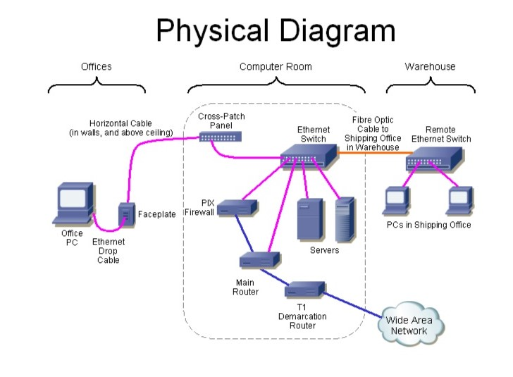
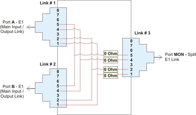
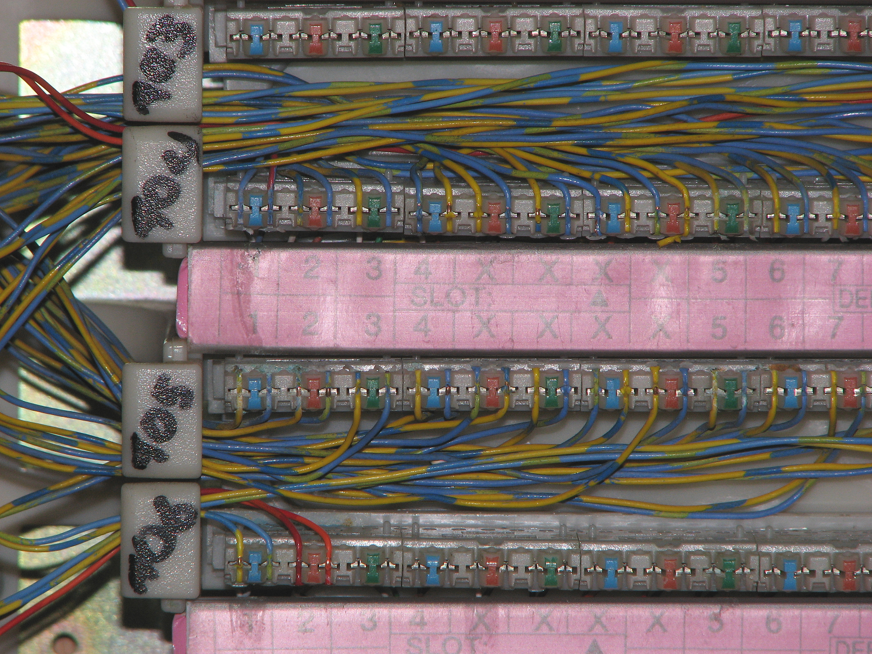
T1 Patch Panel Wiring Diagram
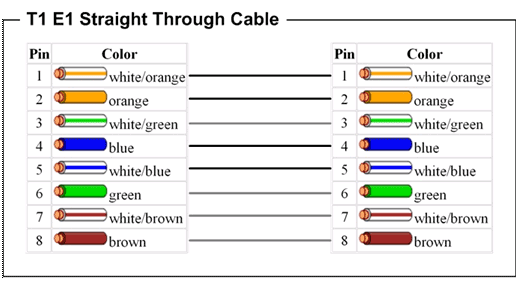
The cat5e patch cable is the basic component to connect end devices to patch panel ports and to connect the ports between two local patch panels.
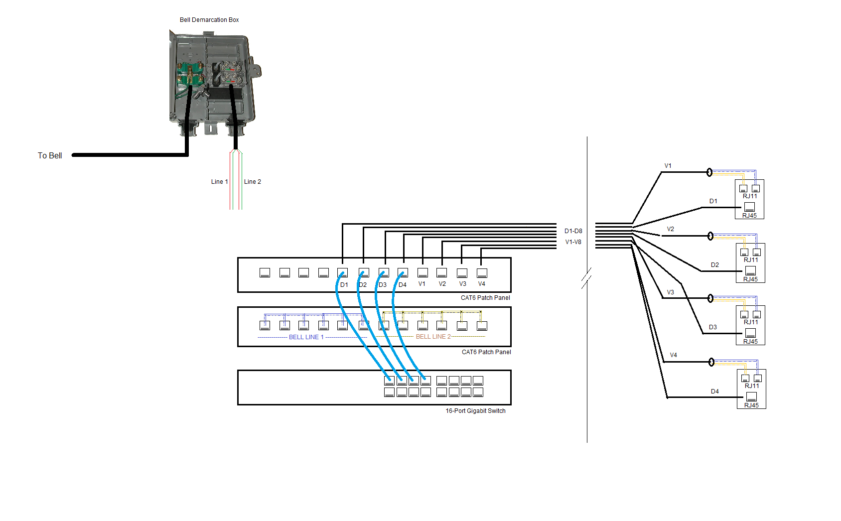
T1 patch panel wiring diagram. How to wire your house with cat5e or cat6 ethernet cable. The t1 panel interfaces cisco atm network modules nm 8t1 ima nm 4t1 ima. Here is a diagram of the keystones and the wire assignments below. I personally recommend dropping another data run for this but if you dont have that option here is a set up you can use.
So i have two building. The jack panel will have rj 45 looking connectors called rj 48c connectors with numbers corresponding to the line cards in the niusmart jack. Most patch panels and jacks have diagrams with wire color diagrams for the common t568a and t568b wiring standards. I need to 4 pair to a cat.
Paperwork that i have received from a third party that will be part of my mpls network. The way the customer interfaces with it is a jack panel that will plug into the cage of ds1t1 cards called the niu it does this with a parallel port looking connector that is prewired to the jack panel. Then theyll patch the circuit from the t1 card either to a 66 block or a rj48x jack. As you can see the wiring diagrams imprinted on the jacks show both the a b wiring methods.
The back of the patch panel also shows both wiring methods as seen below. Pin 3and green to blue pin 4. Fiber optic patch panel wiring diagram together with s filedb experts exchange in ing 2013 07 w31 669467 wiring ether in additionfiberopticshare wp content uploads 2014 11 fibre optic patch panel furthers nhms us wp content uploads 2018 10 fiber optic patch panel wiring diagram impressive patch panel wiring diagram fiber optic 2001 ford f 150 of fiber optic patch panel wiring diagram along. Jon thank you for your article how to t1 circuits and wiring i am currently preparing to extend t1 connections from the demarc to equipment at several locations.
So when wiring the cat5e patch panel a big issue is the design and quality of the terminations of cat5e patch cables. Notice that the blue and brown pairs are identical for both methods. 20215 has 8 rj45 ports on the front which are interfaced with 32 telco compatible wire wrap pins on the back. T1 cisco router cisco router voice output 4 wire pin telephone patch panel goes to the other side of the building another 4 wire pin telephone patch panel voice server.
To be honest i. The t1 patch panel pn. I need to use 4 pair for a t1 one from one end to the other end. When choosing a suitable patch cable booted and non booted is two basic types of plug features.
The upper diagram is 568a and the lower diagram is 568b. Choosing a backup generator plus 3 legal house connection options transfer switch and more duration. Bailey line road recommended for you.


