Timer Relay Contactor Diagram
Time Relay Delay Interclass

How To Wire Pin Timers

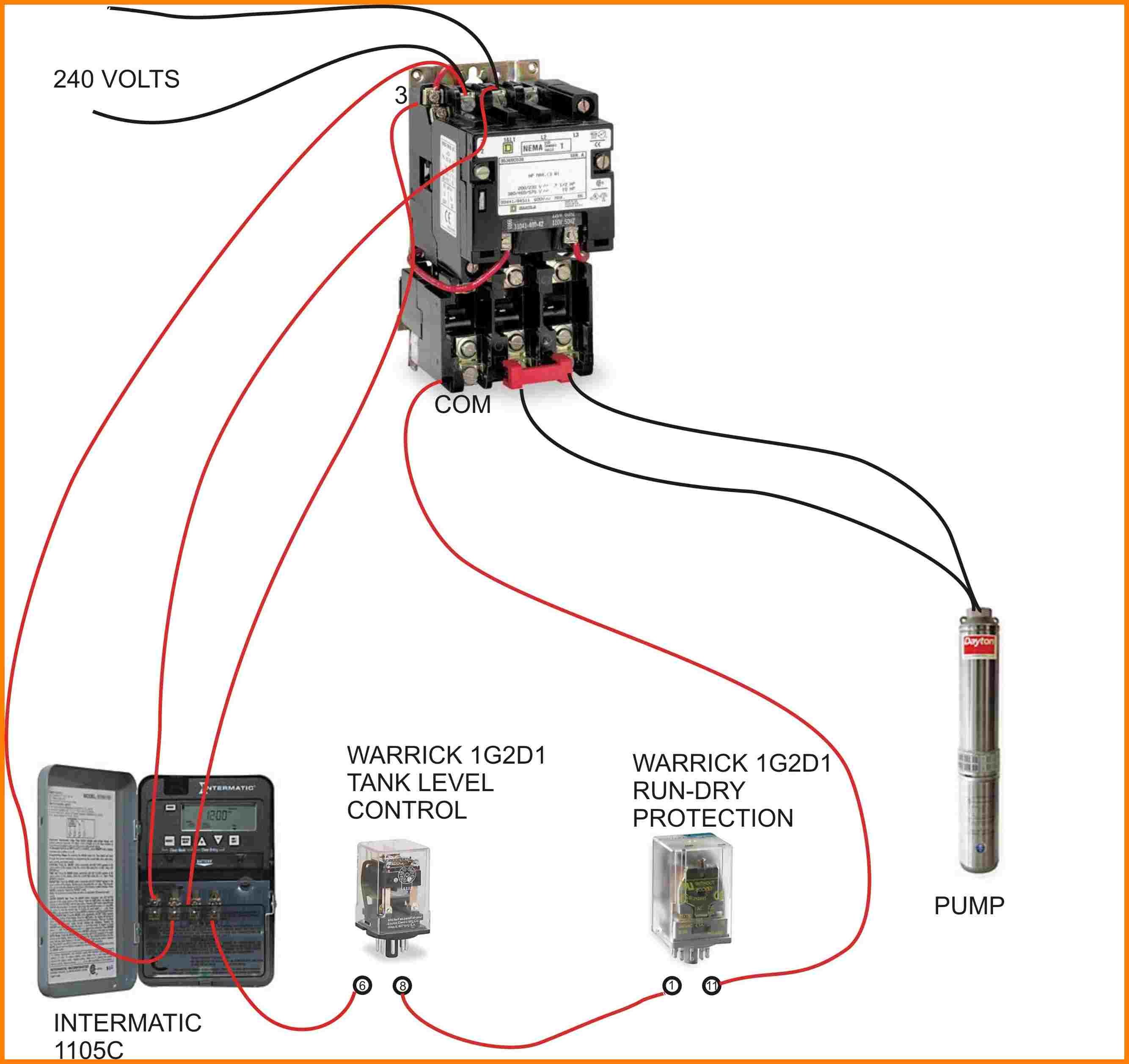
Delay Timer For Motor Or Pump 120volt To 240volt

Time delay relays and solid state timers are used to provide the desired delay and timing functions.
Timer relay contactor diagram. Their purpose is to control an event based on time. Time delay relays are very useful in protecting sensitive electronic devices from spikes and surges. A simple time delay relay circuit is designed here. With the help of this circuit a user controlled delay to relay can be given.
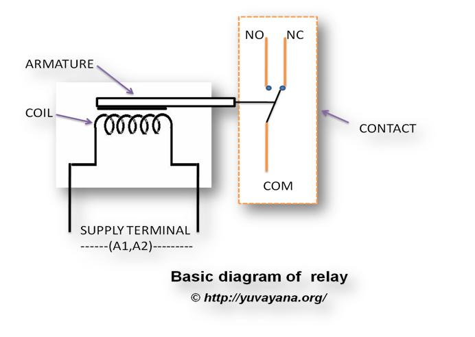
Time delay relays are simply control relays with a time delay built in. Although other parts of the window such as the muntin strips separating panes. Time delay td also begins its timing cycle. A special class of electromechanical relays called time delay relays provide delayed action either upon power up or power down and are commonly denoted in ladder logic diagrams by td or tr designations near the coil symbols and arrows on the contact symbols.
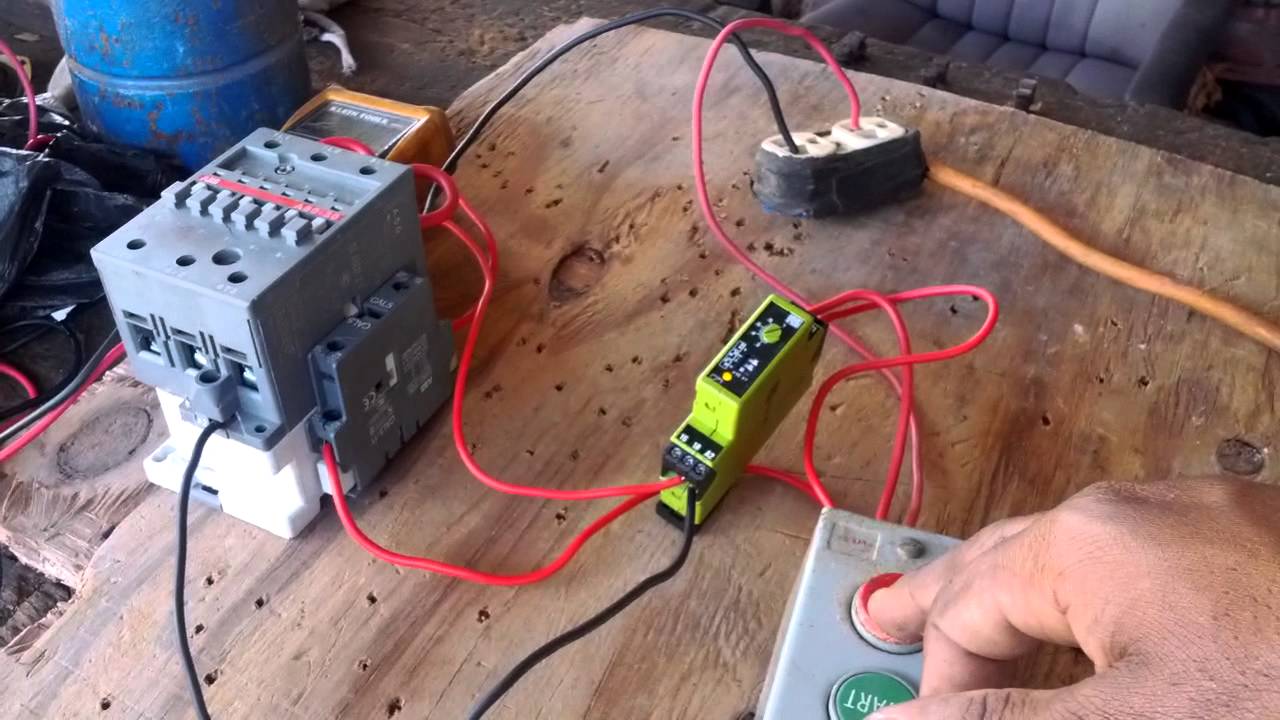
2 days ago i wired 380 to 440 volts contactor for a 3 phase motor and save these images of contactor in pc. Its is important to. Though there are many types of timers and different functions they can perform they all come from two basic types which are on delay timer and off delay timer. We offer a wide range of iec industrial relays designed for heavier duty applications large loads and long life to meet your general industrial control needs.
When designing circuits using time delay relays questions such as what initiates a time delay relay does the timing start with the application or release of voltage when is the output relay energized etc must be asked. Application requirements for time delay relays tdrs david. With multiple mount options models a wide range of input voltage timing range and functionality there are versatile timing relays to meet any timing requirements. Contactor wiring and i hope after this post you will be able to wire a 3 phase motor i also published a post about 3 phase motor wiring with magnetic contactor and thermal overload relay but today post and contactor wiring diagram is too simple and easy to learn.
A simple circuit diagram either of the two start buttons will close the contactor either of the stop buttons will open the contactornote that one one of the contactor acts as a switch for the start button. Safety iec control relays are also available. Tds output contact closes line 6 causing the infrared heaters contactor to close. The electronic timer relays are more versatile than the older mechanical models and less prone to failure.
Here is an example of a. Line 4 it triggers timer td.

Contactor Relay Wiring Wiring Schematic Diagram 39

Pin On Elec

Contactor Relay Wiring Wiring Schematic Diagram 39

Delay Timer For Motor Or Pump 120volt To 240volt

Contactor Relay Wiring Wiring Schematic Diagram 39
Relay Logic Circuit Rlc Relay Contactor Switch And

Industrial Control Basics Part 1 Contactors C3controls

Contactor Relay Wiring Wiring Schematic Diagram 39
How To Wire A Timer In A Control Circuit

Industrial Control Basics Part 1 Contactors C3controls

Using Time Delay Relays To Cycle A Traffic Signal

Time Delay Relays Electromechanical Relays Electronics

Traffic Light Diagram Using Time Relay Magnetic Contactor

Relay Logic Circuit Rlc Relay Contactor Switch And
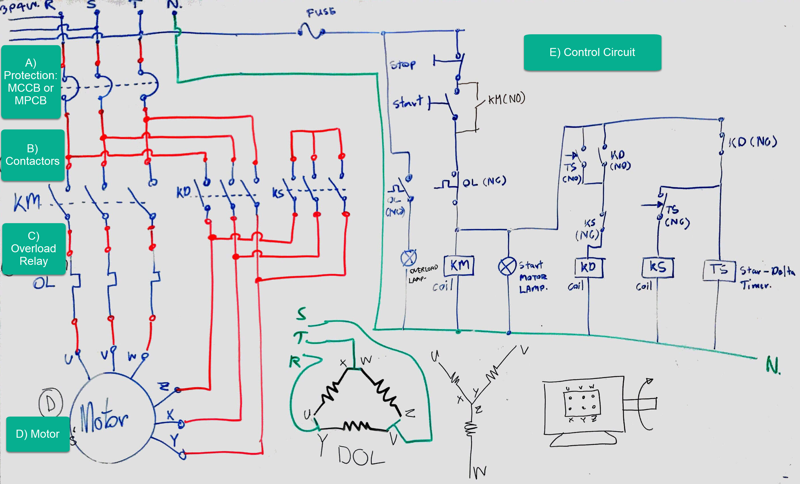
The Beginner S Guide To Wiring A Star Delta Circuit
Contactor Relay Wiring Wiring Schematic Diagram 39

How To Wire Pin Timers
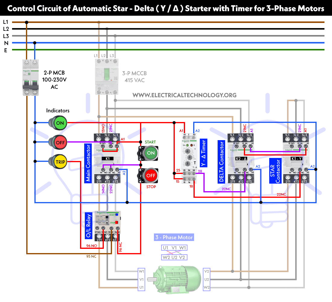
Star Delta Starter Y D Starter Power Control And Wiring
