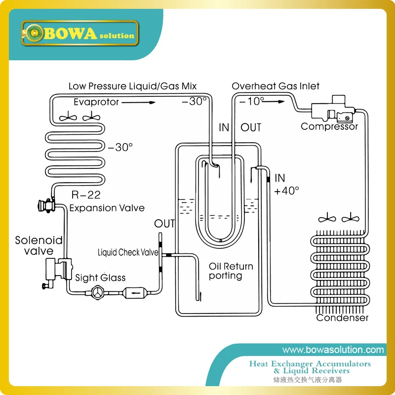
Receiver Refrigeration Wiring Diagram Heated

Condensing unit and refrigeration system installation operations manual r448ar449a 57 02611.
Receiver refrigeration wiring diagram heated. View and download heatcraft refrigeration products condensing units h im cu installating and operation manual online. We have other articles here that will help you with thermostat wiringthese other articles help you with thermostat wiring colors and thermostat wiring diagramsin this article we will provide specific information for wiring a heat pump for control. Wrapped with heat tape and insulated. Dry nitrogen is preferred.
The y6630d is a battery powered wireless room thermostat and mains powered hc60ng receiver box pre bound to give intelligent room temperature control of a single zone. How to wire a heat pump for control there may be a time when you will want to change your old heat pump thermostat with a new heat pump thermostat. Installation and operation manual. Installation service manual parallel compressors enviroguard save these instructions for future reference.
System refrigerant capacity is the receiver capacity as listed in. Hussmann corporation bridgeton mo 63044 2483 usa. Heatcraft refrigeration products condensing units installation and operation manual. Figure 66f05 evaporative condenser should be at higher level than its receiver.
Condensing units h im cu heat pump pdf manual download. Bolts nuts lock nuts pipe heater unit cooler piping. When brazing refrigerant lines an inert gas should be passed through the line at low pressure to prevent scaling and oxidation inside the tubing. As can be seen from the y plan wiring diagram above the switched output from the room stat connects directly with the heating white connection to the motorized valve.
Not related to personal injury indicatess situations which if not avoided could result in damage to equipment. High voltage there may be high voltage on the defrost heater relay and the fan relay. Insulated and heated receiver thermostatically controlled suction accumulator. Unit cooler installation diagram.
These refrigerator systems conform to the commercial refrigeration manufacturers association health and sanitation standard crs s1 86. Wiring at the unit coolers will be as follows see wiring diagrams. In some installations it may be necessary to raise the evaporative condenser to obtain a minimum of 18 drop between the outlet of the condenser and the inlet to the receiver.


